background image

SECTION 3 
OPERATING PRINTER 


52 

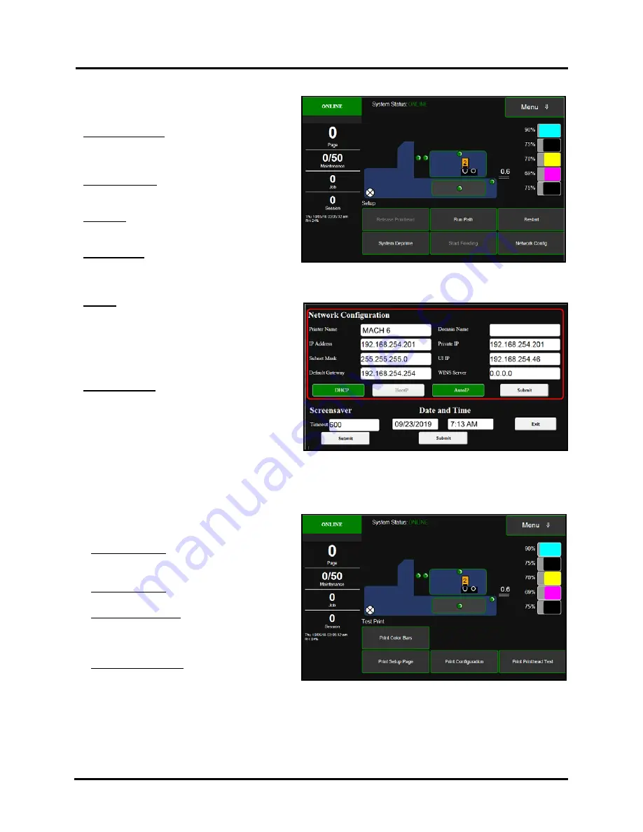
Setup Menu  

Tap the 

Menu button

, then the 

Setup 

button to 

open the 

Setup 

screen.  

Release Printhead 

- Press to Releases Printhead 

Latch.  

NOTE: 

Button is only active when system is in a 

“deprimed” state.


System Deprime

 -


Pumps ink back into Ink 

Tanks (deprimes system) and then releases 
Printhead Latch. 


Run Path 

- Use to clear media from Paperpath 

(printzone)  
without feeding more media.  

Start Feeding 

- Use to “test feed” media. After 

pressing “Run Path” button, to activate printzone 
motor, tap “Start Feeding” button to start/stop Feeder. 

NOTE

: Button is only active after pressing “Run Path” to start printzone motor. 

Restart

 - Shuts-down and restarts the Print 

Engine and Touchscreen without perform long-
term shut-down maintenance routines. Printer 
will still go through normal startup process at 
power-up. This feature is useful when a printer 
re-boot is needed. It takes less time than using the 
normal Shutdown and power-up features. 

Network Config

 - Click to view, enter or change 

settings to connect the Printer to your network. 
See “Connecting Printer via Network (Ethernet 
Connection)” for more details.  
You can also set the 

Printer Date and Time

(

See also System Settings in Using Printer 

Toolbox

.) 


Test Print Menu  

Tapping 

Menu

, then 

Test


Print

 opens the 

Test 

Print 

screen options for printing different reports. 

Print Color Bars

 – Prints a series of 7 color 

bars (

per Printhead

) to indicate how well the 

Printhead is mixing colors and printing. 

Print Setup page 

– Prints a printing pattern 

used for positioning image on the page.  

Print Configuration 

– Prints current Printer 

configuration including Firmware Version, 
Network Connection, Printer Serial Number 
and more for Printer. 

Print Printhead Test

 – Prints color bands, text 

and patterns. Use to check the condition of the 
inkjet nozzles in Printhead. 

NOTE: 

Uses less ink than Print Color Bars.


Summary of Contents for Quadient Rena MACH 6

Page 1: ...Digital Color Inkjet Printer MACH 6 User Guide...

Page 2: ...power cord caused by jamming it between equipment walls or furniture DO NOT remove covers Covers enclose hazardous parts that should only be accessed by a qualified service representative Report any c...

Page 3: ...SB 25 Connecting Printer via Network Ethernet Connection 28 SECTION 3 Operating Printer 31 Media Feed Setup 31 Print Zone Reference Tool 31 Position Media Side Guides Inner and Outer 32 Adjust Sheet S...

Page 4: ...CE SCHEDULE 90 SECTION 5 Troubleshooting Guide 91 Identifying Solving Print Quality Issues 91 Incompatile Paper Type 91 Low Resoution Images Graphics 91 Air in Printhead Nozzle Area 92 Clogged Damaged...

Page 5: ...Tank Door Provides access to Ink Tanks Waste Ink Tray and Clamshell Latch Opening Ink Tank Door disconnects Printer communication to Ink Tanks allowing for safe Ink Tank installation replacement NOTE...

Page 6: ...ccommodate a wider variety of different media widths and lengths They attach to the Rear Media Support Guide 7 6 Feed Rollers twelve Delivers media from Feeder section into Print Engine area 7 Rear Me...

Page 7: ...reen 4 Printhead Cartridge Memjet Printhead produces an 8 77 222 8 mm wide full color print area 5 Service Station Maintains the Printhead The Printhead Assembly lifts and Service Station slides under...

Page 8: ...Tank Door is opened Switch shuts down communication between Printer and Ink Tanks for safe removal and replacement 4 Ink Tanks Printer has 5 Ink Tanks Cyan C Yellow Y Magenta M Black K1 Black K2 Each...

Page 9: ...ead Opening Printhead will be presented in this opening during printing and during Inspect Sled event 7 Exit Starwheel Assembly Starwheels allow for media with freshly printed image to be transported...

Page 10: ...er Tools Choose a location for Printer Unpack and verify Accessory Box contents Remove shipping materials Yellow Zip Ties Foam Block and Shipping Tape Install Print Platen Drip Tray Assembly Attach Me...

Page 11: ...talling removing Print Platen and Drip Tray Assembly Printhead Cartridge and Ink Tanks Distilled Water to clean wet Printhead nozzles Non abrasive lint free Cloths to clean wet Printhead nozzles Paper...

Page 12: ...ackaging in a safe place for possible future use Two people will be required to safely lift printer and place it onto a sturdy level work table IMPORTANT WORK TABLE SURFACE MUST BE LEVEL 2 4 6 1 3 5 C...

Page 13: ...ort Wedge Extensions Narrow and Wide Attach to slots in Rear Media Support Guide Sled 5 AC Power Cord 6 Print Platen Drip Tray Assembly Includes High and Low Print Platens 7 Media Side Guides Inner an...

Page 14: ...the service station sled during transport Do NOT cut the white or black zip ties used to control the position of the ink tubes 4 Be sure to remove all pieces of cut yellow zip ties from the printer 5...

Page 15: ...Drip Tray Low Platen 1 3 dots is for media such as heavy paper envelopes card stock cardboard chip board padded envelopes High Platen 2 4 dots is for thin flexible media such as sheet paper up to and...

Page 16: ...back of Drip Tray is not sitting level check to be sure both tabs are in slots C shown above If front of Drip Tray will not drop into front slot C you may have Drip Tray in backwards Remove and rotat...

Page 17: ...BAR as shown C Align holes in Guide with holes in Mounting Block and install screws to secure Guide NOTE Screws are different Make sure flathead screw 1 is installed into the inner countersunk hole an...

Page 18: ...rear posts Allen screws as shown below Then loosely install Knob thumbscrew and washer D Align holes on top of Guide with holes in the Nuts on Mounting Block as shown below Using the two flathead scr...

Page 19: ...lbox installation process Network Port 3 for connecting printer to a network environment Tip Power up one printer at a time when similar printers are on the same network Once Printer is connected and...

Page 20: ...o Black one Cyan one Magenta and one Yellow The Ink Tank is a delicate precision device Handle with extreme care to avoid damage Ink Tank Anatomy WARNING Ink in Ink Tanks may be harmful if swallowed K...

Page 21: ...on bottom of Latch to release and swing Latch open hinged at top 5 Verify Waste Ink Tray C is securely installed Latched into frame at both sides 6 Remove new Ink Tank s from packaging 7 Insert Ink T...

Page 22: ...eep all other packaging to store dispose of old Printhead Cartridge ATTENTION If you experienced fuzzy print quality or an abrupt failure in a particular area of nozzles on the previous Printhead we r...

Page 23: ...These items will be used to wet the Printhead nozzles NOTE Do NOT use tap water or paper towels to wet or clean the Printhead nozzles Doing so may cause damage to the Printhead Cartridge and possible...

Page 24: ...eleased NOTE If Printhead isn t detected no Printhead currently installed during the power up process the Printhead Latch should automatically release If the Printhead Latch was accidently closed afte...

Page 25: ...below 5 Remove Fluidic Cap Protectors 2 if present on Ink Revolver Couplings Save these items They should be used to seal and protect the open ink system whenever a Printhead Cartridge is not install...

Page 26: ...from Printhead at a 45 to 90 angle DO NOT pull strip at less than a 45 angle from Printhead surface DO NOT allow removed strip to touch Printhead Nozzles 7 Wet Printhead Surface Creates temporary wate...

Page 27: ...le surface re install Printhead and shut Printhead Latch If Printhead is still NOT recognized call for technical support 11 Close Printhead Door Printer will run a priming routine that fills the ink s...

Page 28: ...input output side of Printhead Cartridge 14 If priming results are BAD please perform the following steps Use a lint free cloth soaked but not dripping with distilled water wet Printhead Nozzle Area a...

Page 29: ...if a higher NET Framework version is installed version 3 5 or 4 must also be installed or Toolbox will not open IMPORTANT Before installing Printer software Toolbox and Driver temporarily disable all...

Page 30: ...ck Next 8 Installing Printer Software Software download begins 9 Would You Like to Install This Device Software Click Install 10 Connect your Device Now window appears Connect USB cable between printe...

Page 31: ...nstaller 13 Restart computer to complete installation The S Series Driver should now be available in your Printers and Faxes or Devices and Printers folder Tip To help distinguish between multiple S S...

Page 32: ...hen tap Setup from the drop down list 5 Select Network Config from the choices provided at the bottom of the screen 6 The Network Configuration screen will be open Tip By default the printer is shippe...

Page 33: ...e Network Then click Next Installing Printer Software Searching for printers will briefly appear 13 Printers Discovered window will appear if one or more S Series Printer is found on the Network If mo...

Page 34: ...ns 16 Would You Like to Install This Device Software Click Install 17 Finished software installation Do not check Print Test Page as Printer is not set up yet You can check Set this printer as the def...

Page 35: ...tion of Exit Sensor If your Media doesn t fully cover the Exit Sensor symbol you must select Ignore Exit Sensor in the Touchscreen Job Menu Media Thickness NOTE Exit Sensor is located under the Exit T...

Page 36: ...at it is about 1 32 from the other side of media Tighten locking knob D to secure Side Guide Adjust Sheet Separators 1 Loosen the locking screws located behind Sheet Separators A and raise Separators...

Page 37: ...edia that is 6 to 17 in length Examples Letter sized 8 5 x11 media feeding Short Edge First SEF 9 10 envelopes feeding SEF 9 x12 envelop feeding SEF 10 x13 envelope feeding SEF Wide Media Support Wedg...

Page 38: ...till providing proper media to feed roller contact Guide Sled Positioning Scales Sled Safety Stop Positioning scales are provided for your convenience Once proper Guide Sled positions are determined f...

Page 39: ...t can be stacked into the Feeder Section is determined by the weight and size of the material The feeder section may not feed larger and heavier media when the stack is high The feeder section may not...

Page 40: ...Menu and select Setup From the Setup menu select Run Path This should clear all media from the paper transport section Once media is clear from this area tap Stop Path Reposition the Feeder Entry Sen...

Page 41: ...u Choices and Features for details on accessing Media Setup menu If the Media and media feed position meets all of the following points Ignore Exit Sensor should not be selected Media is positioned so...

Page 42: ...of another envelope or stick to one another Removing Jammed or Misfed Media Clearing a jam or misfeed depends on where it occurred Feed Section Loosen Sheet Separators and remove media Tip If media ma...

Page 43: ...Using the Printer Toolbox following this section NOTICE By default the Printer Touchscreen will go into a screen saver mode screen goes blank if the printer is idle for more than 10 minutes Tap the s...

Page 44: ...needed PRINTING When PRINTING the area directly below the green box will show the name of the job being processed printed PAUSED When job is PAUSED the area directly below the green box will show the...

Page 45: ...ay be needed to find a value that provides adequate head maintenance acceptable print quality with the least amount of interruptions Common settings range from 50 to 250 Values may need to be changed...

Page 46: ...stalled in printer Example S1_Mk2_R1 3 1 0 0 47 Firmware version R1 3 1 and RPI UI file version 0 0 47 Date and Time shows current date and time Example Tue 08 28 18 08 54 55 am August 28 2018 at 8 55...

Page 47: ...nsor valve Printhead etc to display a description or more details about that item Ink Valve Shows current status of Ink Valve open ink closed open air unknown Sensors Door Switches Shows status sensor...

Page 48: ...or dirty connection Install Tank and verify that Ink Tank Latch is securly fastened Try removing and cleaning QA chip contacts on Tank A percentage number shown in red indicates Ink Low Example 4 Tank...

Page 49: ...set up CAUTION Before using this feature you need to make sure the printer has been properly setup to separate and feed the media you are using After pressing Test Path button the printer transport wi...

Page 50: ...Selector small white circle around the circular scale to obtain the desired New Media Thickness value Selected value will be shown next to New NOTE After making any changes to items on this screen the...

Page 51: ...will also be displayed within the Printhead Icon as shown here Tip Media to Printhead contact and image sharpness can also be affected by the Media Thickness setting Before changing the Print Height...

Page 52: ...passing over Exit Sensor Underside of the Media is white or light in color reflective to Exit Sensor Media doesn t have any holes cutouts or dark colors that pass over Exit Sensor Exit Sensor is clea...

Page 53: ...me printing Button label will change from Resume to Pause Tip After you clear an Error during printing you will need to tap Resume to continue printing the job Cancel Job Cancels the current job from...

Page 54: ...Print Job Library To view the Printer s Job Library tap Stored Jobs on the Jobs Touchscreen The Jobs Library opens Use the View button A to change the Library view from Icon to List Use the Search ico...

Page 55: ...rea not used for printing and saves ink NOTE Can be no larger than maximum print width for Printer 8 77 222 8 mm Top Adjustment moves image up or down 5mm up to 200mm down from top left corner of medi...

Page 56: ...eature is useful when a printer re boot is needed It takes less time than using the normal Shutdown and power up features Network Config Click to view enter or change settings to connect the Printer t...

Page 57: ...ice Station Wiper Roller Condition Wiper Saturates with ink conditions and cleans the Wiper Roller to remove dried residue if the Printer is left inactive for long periods of time New Wiper Use this f...

Page 58: ...the Printhead Door The printer will run the Printhead Prime routine which will also condition the wiper roller 7 When Touchscreen shows Online the process is finished System Test NOTE These tests sho...

Page 59: ...ter open Start Menu 2 Click on Toolbox 3 If prompted select the desired Printer from the Available Printers list NOTE If only one S Series Driver is installed on your computer the Available Printers l...

Page 60: ...trol buttons at bottom of screen Drop Down Menu Options There are four Drop Down Menus View Maintenance Service and Test Print The drop down menus are available on every Toolbox screen allowing you to...

Page 61: ...vicing In this example service is performed every 200 pages Idle Timer shows how often automatic maintenance will run when Printer is Idle not being used In this example 2 360 2 elapsed idle minutes 3...

Page 62: ...cursor pops up a description of that icon NOTE When an error is detected the System Status line may show additional details such as DOOROPEN_INK CONTROL BUTTONS located along bottom of screen Provide...

Page 63: ...be adjusted as needed NOTE Idle Maintenance is performed to help keep the Printhead and ink system in good working order for the next time printer is used Wipe Transfer Frequency Sets how often a Wipe...

Page 64: ...is procedure should only be performed by qualified service personnel If this process is not performed properly Printer could be rendered inoperable UPDATE USER INTERFACE This feature is used to update...

Page 65: ...int job s Printer still tracks estimated per page cost and estimated job cost as job is being printed Continuous Use when estimating multiple consecutive jobs Ink Estimation Mode will stay active Prin...

Page 66: ...enu password provides access to more advanced Printer control and maintenance menus For authorized service personnel only Diagnostics This is the screen that opens when you select Service Menus From t...

Page 67: ...op down menu click Service Menus and then click System Settings 2 System Settings screen opens Use Network Settings to view or change settings for your network WARNING If you are currently connected t...

Page 68: ...elect between the following date formats dd mm yy dd mmm yy mm dd yy mmm dd yy yy mm dd yy mmm dd 3 Click Submit Debug Level Set the detail level of the Debug Logs NOTE If experiencing a persistent is...

Page 69: ...me seconds defined by the value for ui_timeout_seconds Default 600 seconds 10 minutes Once in sleep mode the screen will automatically wake up turn ON if it is touched 1 From the Toolbox select View d...

Page 70: ...g Log from your printer A technician may ask you to set the Debug Level to 1 or 2 and reproduce issue before providing them with the Debug Log file All Shows all Debug and Jobs log files available Deb...

Page 71: ...ew status line is provided every few seconds NOTE The information shown in the Scan Sensors screen is meant for use by a technician You may be asked to capture a screenshot of this screen and send it...

Page 72: ...h DI water End Inspection Gives printer back control over Service Station so printer can perform Printhead maintenance and capping Wiper Transfer In this process the wiper roller is rotated to transfe...

Page 73: ...lignments with the page Designed for use with Letter and A4 sized media Print Configuration Prints current Printer configuration including Firmware Version Network Connection Printer Serial Number and...

Page 74: ...ndows It does have some enhancements to help maximize the Printer s ability to print variable addressed pieces quickly and efficiently Windows 8 8 1 and 10 Once job is set up click File then Print Win...

Page 75: ...zes images for printing in most applications NOTE Some applications like Flex Mail may display image boundaries when printed un checking Mask Optimization box eliminates these lines Remember to check...

Page 76: ...nsport speed to achieve higher dot accuracy and provide more dry time before media exits printer This feature is not available when using Best print quality Over Speed Checking the Over Speed box incr...

Page 77: ...nges to print area in relation to media if needed Values can be shown in Inches or Millimeters Please see Using Layout Tab Printing Adjustments on next page for details Watermark A watermark appears a...

Page 78: ...purge bar to be sprayed printed onto flap This feature allows you to adjust the purge bar position in 0 1mm increments to account for extra distance needed to reach actual gap between pieces Tip To d...

Page 79: ...f you need to remove and reload the Printer Driver on the current computer or load the Printer Driver onto a new computer Export Saves custom Printer Driver settings to a holding file Import Use to se...

Page 80: ...plug it from power receptacle Then open or remove Covers 2 Interior Use a vacuum with a soft brush attachment or a can of compressed air to help loosen dust particles NOTE Be careful around Drip Tray...

Page 81: ...ronics Use a clean dry swab to dab surfaces dry B Rubber Rollers and Transport Belts Clean as needed using distilled water with a damp lint free cloth NOTE Be careful not to splash or drip ink on othe...

Page 82: ...riodic Thorough Cleaning of Star Wheel Assembly NOTE This procedure should be performed by a qualified Service person or operator who has been trained on how to properly perform this procedure 1 Remov...

Page 83: ...ck with ink Make sure that it is securly installed tabs locked into frame at both sides 2 Clean QA Chip contacts D with a clean dry lint free cloth Contacts may also be lightly cleaned with a pencil e...

Page 84: ...k Tank into appropriate color slot Push Ink Tank forward firmly and then pull back about an inch Then push Ink Tank forward firmly again This helps to insure that Septum Needles penetrate seals on Ink...

Page 85: ...turn to the cap position when the Inspect Timeout value reaches zero 3 Open the Ink Tank Door 4 Release the Clamshell Latch to open the Clamshell 5 Using a lint free cloth dampened with distilled wate...

Page 86: ...alling Printhead can compromise print quality due to dehydration DO NOT place an unwrapped Printhead on any surface before installing Protect Printhead from scratches dust fibers dirt and other contam...

Page 87: ...nstalling the Printhead and priming the system See section titled Service Station Maintenance If you plan to discard the current Printhead place the Printhead into the old protective packaging and dis...

Page 88: ...nozzle firing at 1600 dpi down length of media the printer is depositing 4 13 liner inches of print per piece At this rate you can expect a yield of approximately 30 000 envelopes before head replacem...

Page 89: ...pect Service Station for possible cleaning or service needs Use a dry lint free cloth to soak up any excess ink from the Wiper Motor Assembly A and Capping Station B Don t wipe or rub the Wiper Roller...

Page 90: ...h ink it is time to replace Waste Ink Tray or absorbent material within Tray 4 Install Waste Ink Tray making sure the tabs A click into the frame to secure the Tray s position Replace Sheet Separators...

Page 91: ...printer should remain semi level at all times during transportation and storage Failure to do so may cause the printer to leak ink 5 Take care to avoid sharp bumps and strong vibrations during the rel...

Page 92: ...e Print Platen Drip Tray Assembly A from printer 3 Carefully remove Print Platen from Drip Tray Clean Print Platen with damp cloth and distilled water then pat dry 4 Empty ink from Drip Tray Drip Tray...

Page 93: ...C Pull on Tabs D to release and slide Waste Ink Tray out of Printer 5 Inspect absorbent material pad within Tray If nearly or completely black with ink replace Waste Ink Tray or pad within Tray 6 Ins...

Page 94: ...INSPECT INSPECT INSPECT CLEAN Capping Station INSPECT INSPECT INSPECT CLEAN Wiper Motor Module INSPECT INSPECT CLEAN Waste Ink Tray Pad INSPECT INSPECT REPLACE PERFORMED BY SERVICE TECHNICIAN Lubricat...

Page 95: ...itable materials such as Inkjet coated stocks all types recommended for best color output Copier Paper Card Stock Kromekote Coated Paper Gloss finish Coated Paper Satin finish Coated Paper Matte finis...

Page 96: ...e and remove air bubbles within the Printhead and Ink Tubes Deprime and Reprime the system Contact Service person to have them inspect the system for possible air leaks damage to ink tubes or ink revo...

Page 97: ...roller causing damage to Printhead Dead nozzles normally due to the nozzles reaching their end of life printed over 125 000 linear inches Possible Solutions Press the Full Clean Printhead button loca...

Page 98: ...e plate due to printer not being level Ink flooding on the nozzle plate due to excessive back pressure in the ink system Wiper Roller is not being cleaned properly by the system This can occur if ther...

Page 99: ...nd image 90 270 or 180 degrees Sometimes the direction of feed and the mechanics of how the media is driven through the printer can have an effect Run Wiper Transfer in Wiper Menu to reduce ink moistu...

Page 100: ...ction of feed and the mechanics of how the media is driven through the printer can have an effect Reduce the amount of ink being sprayed onto the media by setting the print quality to Normal Spraying...

Page 101: ...al the media you are feeding may be too flimsy Problem Poor original image quality less than 300 dpi Solution Use high quality images Problem Choosing to print image in low resolution from software ap...

Page 102: ...ace causing ink level sensor to give a premature Out condition Clean prism on Tank See section titled Cleaning Ink Tank Contacts Prism Place printer on stable level surface Replace Ink Tank Ink Level...

Page 103: ...ated or is not turning Using Clean Printhead features too often can over saturate wiper roller Print 5 or more Print Color Bars test pages to clear color mixing If problem returns after printhead main...

Page 104: ...Zone If printer is printing image should show on 8 5 wide media Once you see where image is located adjust media or print position as needed Open Clamshell and check Printhead Opening Media may have...

Page 105: ...mage distortions Double sheets Misfeeds Media hesitating or skewing Adjust Sheet Separators Check adjust Media Thickness Try using low 3 dot Print Platen Verify that Print Platen Drip Tray Assembly ar...

Page 106: ...electrical contacts Reinsert Printhead Replace Printhead If problem persists contact technical support Multiple Inks Low Reorder Ink Multiple Ink Tanks Out Replace empty Ink Tanks Multiple Ink Tanks a...

Page 107: ...r pop Ink Tank in and out to improve connection Check clean Ink Tank contacts Tap Clear Error and then tap Resume button from Job Menu to resume printing System Status Crit 63 03 phead offline cancelp...

Page 108: ...lace empty Ink Tank s Verify that Ink Tanks are seated firmly and latches are fully closed Close the Ink Tank Door and tap Clear Error The ink levels should fill in Tip A premature visible ink Out con...

Page 109: ...r check clean the Sled and Lifter Home Sensors If problem persists call for Service CAUTION After pressing Clear Error the system will try to drive the sled lifter or wiper motor again If the same err...

Page 110: ...ickness Guides and Separators Reposition media or Feeder Entry Sensor Assembly so paper passes under sensors System Status PAPERPATH_PAPERJAM Paper Media jam detected Printer has detected that one or...

Page 111: ...Door open Printhead priming process has failed After installing Printhead you must close Printhead Latch and close all doors to start priming process Remove Printhead Cartridge wet print nozzles using...

Page 112: ...Display monitor and control printer via Touchscreen DATA STORAGE Up to 60 GB of onboard Printer storage for Job Library reprint stored jobs via Touchscreen PRINT TECHNOLOGY Memjet Thermal Inkjet Memje...

Page 113: ...ial only 123 2491 OPTIONAL HARDWARE PART Conveyor Stacker with Drop Tray TB 390 Extended Rear Media Support Guide Increases max media length up to 19 for stiff media and up to 22 for flexible media 47...

Page 114: ...Backed up Print Jobs will be located under the prns directory on the USB Flash Drive Backed up Log files will be located in the root directory Log files are in a zipped tgz format These files can be...

Page 115: ...ity Best or Print Quality Normal with Half Speed ON The Kit includes 1 Side Guide Extension Assembly 1 Narrow Rear Guide 1 Thumbscrew 3 Phillips head screws Tools Needed 2 Phillips screwdriver How to...

Page 116: ...a Support Guide plate Tools Needed Phillips screwdriver How to Install the Extended Rear Media Support Guide 1 Remove 2 screws A securing the original Rear Media Support Guide Sled Assembly to the Cen...

Page 117: ...loosely install the Locking Knob removed in Step 2 b Install 2 screws A removed in Step 1 to secure the front of the Assembly to the Center Plate IMPORTANT Be sure to align the Nuts on Mounting Block...

Page 118: ...flap from opening catching or skewing the envelope Helps prevent misprints and media jams Use 1 2 or more as needed for your print job NOTE It is strongly recommended that the Assembly be used in pair...

Page 119: ...ssembly 1 Exit Wheel Shaft 2 Mounting screws This optional accessory provides the ability to position the Wheel Assemblies so they avoid rolling over freshly printed surfaces which can reduce or elimi...

Page 120: ...top of the Wiper Motor Assembly 3 removes excess ink and debris from the Printhead The Service Station Tray 6 captures and removes waste ink that is produced during the Printhead maintenance processes...

Page 121: ...ng Station B out of the Printer NOTE Be careful watch for dripping ink Do not lose the 2 inserts the Capping Station rests on located behind the release tabs 6 Cleaning Remove ink and debris using a s...

Page 122: ...nection D 7 Lift the Wiper Motor Assembly E out of the Printer NOTE Be careful watch for dripping ink Do not lose the 4 springs that the Wiper Motor Assembly rests on 8 Cleaning Remove ink and debris...

Page 123: ...h 4 Remove Wiper Motor Assembly and Capping Station as described in previous sections 5 Remove the Non Operator Side Bracket B secured using two Philips head screws Clean the opening of the Siphon Hos...

Page 124: ...t Then lift the Wiper Roller out of the Wiper Roller Assembly 4 Remove protective covering from new Wiper Roller 5 Install new Wiper Roller Make sure gear on Roller engages gear in Wiper Motor Assembl...

Page 125: ...twork 2 15 Printer 15 USB 2 15 26 Contents of Packaging 9 Control Buttons 58 Control Panel Soft Power Button 1 Touchscreen 1 39 Copies 71 Couplings Ink Revolver 3 Covers Exit Transport 1 Custom Size 7...

Page 126: ...G Getting Acquainted 1 Entry End 2 Front View 1 Ink Tank View 4 Print Engine View 3 Print Zone View 5 Guide Sled Positioning Scales 34 Guides Media Side Guides 2 Media Support Wedge Extensions 2 Rear...

Page 127: ...lean 77 Reflector 5 Media Setup 46 Media Side Guide Inner 2 Media Side Guide Outer 2 Media Side Guides 32 Media Size 71 Media Support Wedge Extension 33 Media Support Wedge Extensions 2 Media Thicknes...

Page 128: ...ort Rollers 5 Misfeeds 38 Optional Hardware 109 Paperpath Surface 5 Print Platen Drip Tray Assembly 11 Receptacle Power 2 Sheet Separators 2 Shipping Transporting 87 Star Wheels Clean 78 Supplies 109...

Page 129: ...Printer 87 Shutdown Toolbox 68 Sled Error 105 Sled Motor 3 Sled Safety Stop 34 Small Media Guide Kit 111 Soft Power Button 1 Solving Print Quality Issues 91 Specifications 108 Star Wheels Clean 78 St...

Page 130: ...er 53 Touchscreen Display 39 Transport Inspection 7 Troubleshooting Ink Tanks 98 Printer 100 101 Printhead 99 Troubleshooting Guide 91 Turning Power ON OFF 15 U Unpacking 8 Update User Interface 60 Up...

Page 131: ......

Page 132: ...2 1 2020 Quadient April 9 2020...

Reviews: