


1-10
Connecting cables
Operation Manual for the EMT 10T, 10/4, and 10/4T
Melco Embroidery Systems
Connecting cables
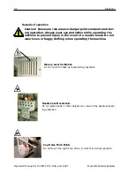
Power requirements
Melco suggests using a dedicated line with a line conditioner (available from Accessory Resource
Corporation). Do not use any power cable that appears to be damaged. If your power cable
appears to be damaged, order a new power cable from your Melco representative.
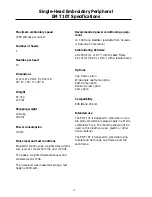
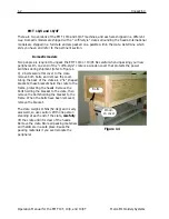
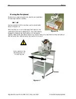
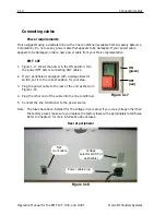
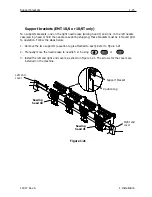
EMT 10T
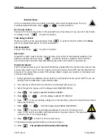
1. Figure 1-17 shows the power in the ON position. Turn
the power OFF before connecting ANY cables.
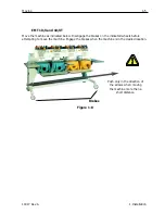
2. If your peripheral is equipped with a voltage selector
switch, set it to the correct position for your area.
3. Plug the power cable to the rear of the unit as shown in
Figure 1-18.
4. Plug the other end of the cable into the line conditioner.
5. Connect the line conditioner to the power source.
Note: The fuses have been installed for the voltage in your area; if you use a voltage other than
the factory preset, make sure you replace the factory fuses with appropriately rated fuses.
Refer to Chapter 4 for more information about fuses.
Figure 1-18
Net-
work cable
Voltage
selector switch (if
applicable)
Rear of peripheral
Power cable plug
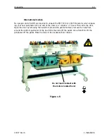
Figure 1-17
ON
(green)
OFF
(red)
Summary of Contents for EMT 10/4
Page 52: ...2 28 Quick Start Operation Manual for the EMT 10T 10 4 and 10 4T Melco Embroidery Systems ...
Page 108: ...6 10 Error Messages Operation Manual for the EMT 10T 10 4 and 10 4T Melco Embroidery Systems ...
Page 126: ...INDEX Operation Manual for the EMT 10T 10 4 and 10 4T ...
Page 127: ...Quick Ref erence Guide for the EMT 10T 10 4 and 10 4T 11817 Revision A ...