28
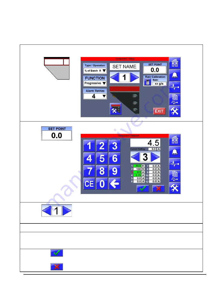
Entering Component Settings
Settings are entered from the Home Screen by pressing any of the enabled component
hoppers shown on the home screen.
Press
One of the hoppers
Display will show the Component Setup screen.
Press
Display will show the Component Setpoint screen.
Press
To navigate through all enabled components. The numbers
correspond to the numbered physical hopper or feeder on the
blender. If you are not sure what component number operates what
hopper or feeder, see Manual Operators to confirm components.
Press
The Keypad
To enter the desired setting for the selected Component.
As each setting is entered the recipe overview table will highlight each changed setting in green.
Navigating through the recipe will also display the Original Setting below the Setting field at the top.
Press
OR
to save the settings and load the recipe and return to the
Home Screen.
Press
to cancel the new settings and revert back to the original
settings. Display returns to the Home Screen.
Summary of Contents for FLEXBUS Lite
Page 6: ...6...
Page 10: ...10 Blender Parts Key...
Page 13: ...13...
Page 100: ...100 Technical Drawings...
Page 101: ...101...
Page 102: ...102...
Page 103: ...103...
Page 104: ...104...
Page 105: ...105...
Page 106: ...106...
Page 107: ...107...
Page 108: ...108...
Page 109: ...109...
Page 110: ...110...
Page 111: ...111...
Page 112: ...112 FCA INSTALLATIONDIAGRAM...
Page 113: ...113 WSB 4088 IO wiring diagram 120V...
Page 114: ...114 D WSB E0001 Electrical Diagram WSB Export Single Phase...
Page 115: ...115 D WSB E0002 Electrical Diagram WSB Export 3 Phase...
Page 116: ...116 D WSB E0003 Electrical Diagram WSB Export 1800 3 Phase...
Page 117: ...117 D WSB E0004 Electrical Diagram WSB Export Maxibatch...
Page 118: ...118 D WSB P0001 Pneumatic Diagram WSB with Non Removable Hoppers...
Page 119: ...119 D WSB P0002 Pneumatic Diagram WSB with Removable Hoppers...
Page 120: ...120...
Page 138: ...138 Flexbus Lite Wiring Diagrams...
Page 139: ...139...
Page 140: ...140 Flexbus Lite Component Map...


