Maintenance
47
Subject to technical changes.
200114
BA-42820-02-V03
Water sampling station
EASYPRO
Operating instructions
Perform the following work steps:
1.
Working in the main menu, navigate to System > Service > Device.
2.
Press Software update.
3.
Select the *.BIN file with the newer version and press “Load“.
4
The software is installed. The device will restart automatically during
this procedure.
ü
Update performed
11.8 Battery
The device is fitted with a button cell. Check the button cell within the
scope of the annual maintenance. The lifetime of the button cell is deter-
mined by the device usage and can vary considerably.
You will need to replace the battery more often with devices which are
switched off often or over a long period (e.g. over winter).
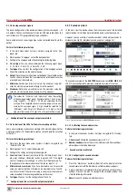
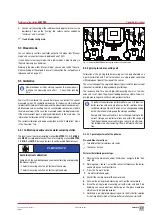
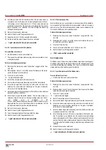
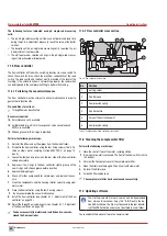
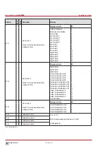
Fig. 34: CR1220 button cell
11.8.1 Checking the charge
You can check the battery charge easily using the device. Replace the
battery if the charge amounts to less than 2.9 V.
è
Working in the main menu, navigate to System > Information > Sys-
tem values and read the current charge state of the battery.
11.8.2 Replace the battery
You must remove the two input circuit boards to be able to replace the
battery (Fig. 34 „CR1220 button cell“ on page 47).
Pre-conditions for actions:
ü
The voltage supply has been disconnected and protected against
re-connection.
ü
The housing is open.
Resources required:
@
Socket wrench 5.5 mm (M3)
@
New battery: CR1220, Ø12,5 mm, 3 V, 35 mAh
Perform the following work steps:
1.
Pull all cable connections from the input circuit boards which you
need to dismantle.
2.
Using the socket wrench, unscrew the retaining nuts from the white
protective plate and remove the plate.
3.
Using the socket wrench, unscrew the two nuts from the input circuit
boards which you need to remove.
4.
Working carefully, slide the input circuit boards from their brackets.
4
The battery is now easily accessible.
5.
Lever the battery out of its holder without damaging the contact bow.
6.
Slide a new battery in the holder.
ü
The battery has been changed.
11.9 Replacing the fuse
Your device is fitted with an electrical fuse to protect against short circuits
or over-voltage. You can change the fuse if it is defective.
8
1
9
2 3 4 5 6 7
10 11121314151617181920
2930313233343536
2122232425262728
37383940
41 42 43
44 45 46 47 48 49 50 51 52
USB
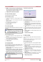
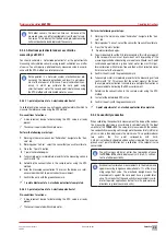
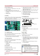
Fig. 35: Position of the fuse
Pre-conditions for actions:
ü
The voltage supply has been disconnected and protected against
re-connection.
ü
The housing is open.
Resources required:
@
Slotted screwdriver
@
New fuse: 5 x 20 mm, 3.15 A, 250 V (delay)
Perform the following work steps:
1.
The fuse holder in the form of a bayonet catch is located at the bot-
tom right-hand side, above the clamps for PE, N and L with the mark-
ing “Fuse”. Use the slotted screwdriver to press the catch down-
wards and then turn it leftwards.
2.
Remove the fuse.
3.
Replace the fuse and fix it in place by turning the catch clockwise.
ü
Fuse has been replaced.
11.10 Resetting the settings
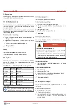
i
The instructions differentiate between the internal factory set-
tings and the device configuration.
The factory settings contain the basic configuration of the de-
vice hardware and cannot be changed.
The configuration file (*.SET) contains the individual device
configuration. You can change, save and load the individual
settings.
Internal fuse

