Installation
24
BA-42820-02-V03
Water sampling station
EASYPRO
Operating instructions
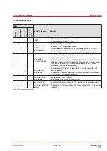
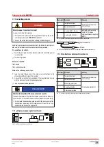
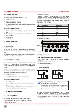
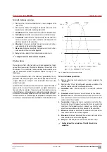
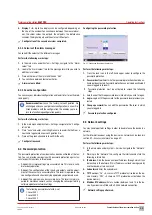
7.7.3 Current module input circuit board
A number of sensors require an operating voltage for their measurement.
These sensors are connected to the current module and supplied with 24
V.
4
3
2
1
5
Fig. 18: Current module input circuit board
Terminal
Function
Sensors
1
Temperature input
Resistance thermometer TE110/
Pt100
2
Temperature input
3
-
-
Excess chlorine measuring cell
CS120/conductivity measuring cell
4
+ for CS120**
-
for 0/4 − 20 mA
Total chlorine measuring cell GCM/
diaphragm-covered measuring cell
Cl 4.1/diaphragm-covered
measuring cell CD 4 MA*
5
+ 24 V DC output
Tab. 24: Terminal connection of the current module input circuit board
* Requires 24 V supply module
**red: +; blue, purple: -
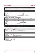
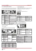
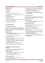
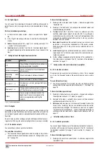
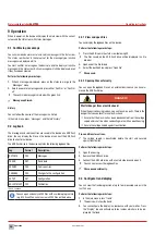
7.7.4 Conductive input circuit board to the conductivity
module
79889_1
Bild BA Eingangsmodul Leitfähigkeit
TOPAX MC Salzgehalt
1
2
3
4
Fig. 19: Conductive input circuit board to the conductivity module
Termi-
nal
Function
Sensors
Wire colour M12
connection cable
1
Temperature input
Conductivity
measuring
(conductive), k=1
black (BK)
2
Temperature input
blue (BU)
3
Conductivity
measurement
input
brown (BN)
4
Conductivity
measurement
input
white (WH)
Tab. 25: Terminal connection of the conductive input circuit board to the conductivity module
DIP switch
0 - 2000 μS/cm 0 – 20 mS/cm
0 – 100 mS/cm
1
OFF
ON
ON
2
OFF
ON
ON
3
OFF
OFF
ON
4
OFF
OFF
ON
Tab. 26: Selecting the measuring range
7.8 Connecting the actors
Depending on the equipment of the device, you have various possibilities
of actuating actors such as dosing pumps or regulation valves.
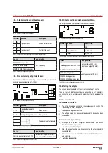
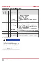
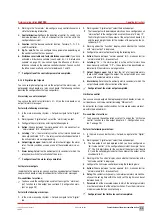
7.8.1 Alarm relay
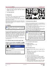
The alarm relay on the main board forwards alarms.
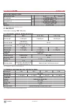
41 42 43
Fig. 20: Alarm relay
Terminal Function
Description
41 + 42
normal on
The relay works on these
clamps as an opener.
42 + 43
normal off
The relay works on these
clamps as a closer.
Tab. 27: Terminal connection of the alarm relay
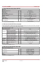
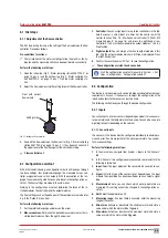
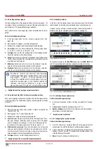
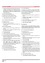
7.8.2 Output circuit board with relay
4
3
2
1
Fig. 21: Output circuit board with relay
Terminal Function
Description
1
Relay X.2
Second digital output
2
3
Relay X.1
First digital output
4
Tab. 28: Clamp connection of the output circuit board with relay
Actors
Configuration
MAGDOS dosing pumps
On/Off
MEMDOS dosing pumps
On/Off
MEMDOS SMART dosing pumps
On/Off
MIDIDOS/MINIDOS dosing pumps
On/Off
Peristaltic pumps
Pulse length
Tab. 29: Actors and relay configuration

