Commissioning of the water sampling station
33
Subject to technical changes.
200114
BA-42820-02-V03
Water sampling station
EASYPRO
Operating instructions
2.
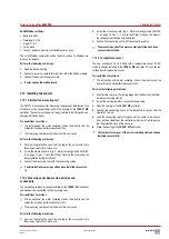
Working in the “Parameter” tab, configure every control channel and
state the following information.
3. Control direction:
Configure the direction of control. If a switch is to
be made between a 1- and a 2-side control, this must be set in the
configuration assistant.
4. Function:
Set the desired controller function. Possible: P-, PI-, PD-
and PID-controller.
5. Xp, Tn, and Tv:
You can configure these parameters depending on
the control function that has been set.
6. Disturbance variable and factor disturbance variable:
If you have
activated a disturbance variable (see chapter 8.3.1.4 „Disturbance
variable“ on page 30), you can configure the influence of this dis-
turbance variable on the selected controller channel. You can switch
the influence on or off and set a factor between 0.1 and 10.
ü
Configuration of the controller parameters completed.
8.3.2.4 Digital output signals
You can use digital output signals via the outputs of the alarm relay, an
optocoupler circuit board or a relay circuit board. The following sections
describe the configurations that you can perform.
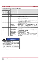
Alarm relay as an alarm output.
You can use the alarm relay (terminals 41 – 43) on the main board as an
output for alarm messages.
Perform the following work steps:
1.
In the main menu under System > Outputs, navigate to the “Digital”
tab.
2.
Working under “Digital output”, select the “alarm relay” output.
3.
Configure the alarm relay by entering the following data.
4. Action:
Choose between “normal opened” (N.O., make contact) or
“normal closed” (N.C., break contact).
5. Latching:
“On “= the alarm relay is active until all alarms have been
manually confirmed. “Off” = the relay is automatically deactivated if
the active alarms are no longer pending.
6. Output triggers upon:
Select which alarms should trigger the alarm
relay. The relay switches as soon as one of the selected alarms is ac-
tive.
7. Alarm delay:
Determine the earliest point (in seconds) at which the
relay should switch after activation of the alarm.
ü
Configuration of the alarm relay completed.
Further alarm outputs
In addition to the alarm relay, you can use the unused outputs of the opto-
coupler circuit board or relay circuit boards for further alarm messages.
Pre-conditions for actions:
ü
You have used the configuration assistant to assign the “alarm out-
put” function to a free output (see section8.2 „Configuration assis-
tant“ on page 29).
Perform the following work steps:
1.
In the main menu under System > Outputs, navigate to the “Digital”
tab.
2.
Working under “Digital output” select the desired output.
4
The free outputs will be displayed which you have configured as an
“alarm output” in the configuration assistant. Example: “Relay 1.2”.
The first digit stands for the number of the output circuit board (1.X)
and the second digit stands for the number of the output on the cir-
cuit board (X.2).
3.
Working under the “Function” display, check whether the function
with “alarm output” is displayed.
4.
Configure the alarm output by entering the following data.
5. Action:
Choose between “normal opened” (N.O., make contact) or
“normal closed” (N.C., break contact).
6. Latching:
“On “= the alarm output is active until all alarms have
been manually confirmed. “Off” = the output will be deactivated au-
tomatically if the alarms are no longer active.
7. Output triggers upon:
Select from the list of all possible alarms
those which should trigger the output. The output switches as soon
as one of the selected alarms is active.
8. Alarm delay:
Determine the earliest point (in seconds) at which the
output should switch after activation of the alarm.
ü
Configuration of the alarm output completed.
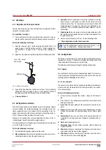
Limit value control
You can use unused outputs from optocoupler circuit boards or relay cir-
cuit boards as a limit value control (including “DIN contact”).
An output for limit value control switches if all measured values are locat-
ed within the defined limits.
Pre-conditions for actions:
ü
You have used the configuration assistant to assign the “limit value
control” function to a free output (chapter 8.2 „Configuration assis-
tant“ on page 29).
Perform the following work steps:
1.
In the main menu under System > Outputs, navigate to the “Digital”
tab.
2.
Working under “Digital output” select the desired output.
4
The free outputs will be displayed which you have configured as
“limit value control” in the configuration assistant. Example: “Relay
1.2”. The first digit stands for the number of the output circuit board
(X.1) and the second digit stands for the number of the output on the
circuit board (X.2).
3.
Working in the “Function” display, check whether the function with a
“limit value control” is displayed.
4.
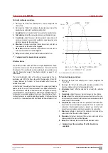
Configure the limit value control by entering the following data.
5. Action:
Choose between “normal opened” (N.O., make contact) or
“normal closed” (N.C., break contact).
6. Delay:
The contact switches only if all water parameters are continu-
ally over the set lag time within the limits set. The lag time can be set
between 0 and 10.
7. Parameter:
Set the measured values in which the water parameters
must be located so that the output switches. Press the minimum or
maximum value that you wish to change.
ü
Configuration of the limit value control completed.

