Commissioning of the water sampling station
29
Subject to technical changes.
200114
BA-42820-02-V03
Water sampling station
EASYPRO
Operating instructions
8.1 First steps
8.1.1 Adjustment of the flow controller
The first step during start-up is the setting of the flow volume on the flow
controller. Proceed as follows.
Pre-conditions for actions:
ü
The installations of the water sampling station, the electrics, the hy-
draulics and the measuring cells have been performed successfully.
Perform the following work steps:
1.
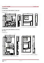
Open the inflow tap (Fig. 2 „Water sampling station EASYPRO 4“ on
page 10, pos. 5) and the outflow tap (Fig. 2 „Water sampling sta-
tion EASYPRO 4“ on page 10, pos. 12) on the water sampling sta-
tion.
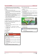
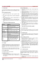
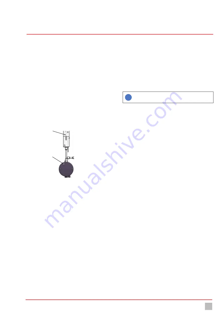
2.
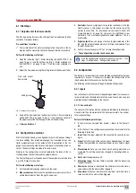
Adjust the flow volume using the setting screw of the flow controller.
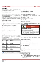
Float with correct
flow volume
Setting screw
Fig. 27: Setting the flow controller
3.
Read off the flow volume on the flow control (Fig. 2 „Water sampling
station EASYPRO 4“ on page 10, pos. 2). It has been set correctly if
the upper level of the float lies against the notched marking.
ü
Flow controller set.
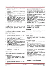
8.2 Configuration assistant
With initial commissioning, a configuration wizard will lead you through
the basic settings: Your preferred language, the measured values, con-
troller assignments and switch outputs. With the exception of the lan-
guage, the values configured here can only be set in the configuration as-
sistant. The finer settings are made in the sub-menus.
Working in the configuration assistant, determine the tasks of the in-
stalled modules, the controller and the output modules.
The finer settings such as the behaviour of these modules are made later,
e. g in the “Outputs” menu item.
Perform the following work steps:
1.
Set the preferred language and press on the arrow.
2. Measured values:
Determine the desired measured value for the in-
stalled input modules. Press the right-hand arrow.
3. Controller:
You can assign inputs for up to four controllers in this tab.
Select a sensor, a virtual input or a timer. Set the centre row of the
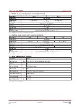
control function (Tab. 18 „Multi-channel controller TOPAX® MC
measuring inputs“ on page 16) and press the right-hand arrow.
Controllers 1 to 4 must be assigned to the output modules 1 to 4 in a
fixed fashion.
4. Digital outputs:
You can assign a function to output modules in this
tab. Only the output modules which are still free are displayed. Press
the right-hand arrow.
5.
Confirm the security query with “Yes” to save the configuration.
ü
The configuration assistant has been ended.
i
Start the configuration assistant manually in System > Set-
tings > Configuration > “Configuration assistant”.
8.3 Configuration
The device is set up variably and can be individually adapted to meet your
requirements. As such, it is necessary to adjust the configuration of the
inputs and outputs to the sensors and actors used.
The following section leads you through the device configuration.
8.3.1 Inputs
You can connect up to four sensors (depending on model) for various wa-
ter parameters and the temperature to the device. You can also use up to
eight digital inputs (depending on the version).
8.3.1.1 Sensor inputs
The sensors in the device must be configured individually to enable pre-
cise and error-free measurement of the water parameters. You can per-
form various settings.
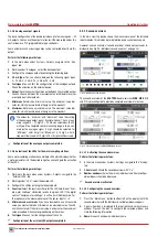
Perform the following work steps:
1.
In the main menu, navigate from System > Inputs to the “Sensors”
tab.
2.
In the “Sensors” tab, configure every connected sensor and state the
following information.
3. Input:
Select the input module of the sensor which you wish to con-
figure.
4. Signal:
Enter the type of the sensor signal. Depending on the input
module, the signal type has been specified or you can select a signal
type.
5. Measurement:
Here, you can check which water parameters are
measured. This setting can only be changed in the configuration as-
sistant.
6. Unit:
Select the appropriate unit.
7. Measuring range:
If an input field is available, enter the measuring
range of the sensor.
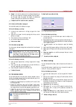
8. Min-alarm:
Activate or deactivate the minimum alarm and state a
value under which the alarm will be triggered.
9. Max-alarm:
Activate or deactivate the maximum alarm and state a
value over which the alarm will be triggered.

