Maintenance
46
BA-42820-02-V03
Water sampling station
EASYPRO
Operating instructions
The following features indicated used pH single-rod measuring
cells:
n
The pH single-rod measuring cell takes an extraordinarily long time
during the pH 6.8 adjustment process to reach the value of the buffer
solution.
n
The deviation of the pH single-rod measuring cell is too wide; the pH
6.8 adjustment is not possible.
n
The white potassium chloride salt rings in the pH single-rod measur-
ing cell are exhausted or discoloured.
11.5 Flow controller
The flow controller is fitted with a switching function via a reed switch. To
check the switch function, check the electrical conductivity of the reed
switch. The reed switch and the float must be located at the level of the
marking. If the switch function is not working properly, the reed switch
can be displaced in the compression fitting to perform fine tuning.
11.5.1 Performing the annual maintenance
The flow controller must be subject to annual maintenance in order to
guarantee its functionality.
Pre-conditions for actions:
ü
Throughflow was deactivated.
Resources required:
@
A maintenance set is available.
@
Suitable tools (e.g. a Ø 3 mm face spanner and a socket wrench
AD19) are available.
@
Silicone grease for the O-rings is provided
Perform the following work steps:
1.
Deinstall the inflow and outflow pipes from the flow controller.
2.
Dismantle the flow controller using the four fixing screws (Tab. 5 „Po-
sition numbers water sampling station EASYPRO 4“ on page 10,
pos. 4).
3.
Loosen the four housing screws on the rear-side of the flow controller
and open carefully.
4.
Replace all the O-rings in the flow controller. Lightly grease all the
new O-rings with silicone grease before insertion.
5.
Replace the diaphragm.
6.
Check all further components for visible wear and replace if neces-
sary.
7.
Clean the components and the housing interior carefully using clear
warm water.
8.
Close the flow controller using the four housing screws.
4
You have completed the annual maintenance.
9.
Install the flow controller (see chapter 8.1.1 „Adjustment of the flow
controller“ on page 29).
10.
Adjust the throughflow volume again (see chapter 8.1.1 „Adjustment
of the flow controller“ on page 29).
ü
You have successfully maintained, installed and re-commis-
sioned the flow controller.
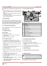
11.5.2 Flow controller cross section
Fig. 33: Flow controller cross section
No.
Position
1
Setting screw
2
Control cone
3
Compression spring
4
Control nozzle
5
Valve at the extraction point
6
Compression spring
Tab. 42: Position numbers flow controller cross section
11.6 Cleaning the sample water filter
Perform the following work steps:
1.
Close the shut-off taps of the water sampling station.
4
Now no more water is conveyed. The float of the flow switch sinks to
the bottom.
2.
Unscrew the transparent cover of the sample water filter.
3.
Clean the filter sieve thoroughly. Then rinse it with clear water.
4.
Re-insert the filter sieve.
5.
Screw the filter cup back on.
ü
The sample water filter has been cleaned successfully.
11.7 Updating software
i
The most up-to-date firmware version can be downloaded
from www.Lutz-Jesco.com. Copy this *.BIN file onto the de-
vice USB flash drive. The file must be saved in the root directo-
ry of the USB flashdrive and may not be stored in a sub-folder.
You can update the device software to a newer version.
6
5
4
2
1
3

