Product description
10
BA-42820-02-V03
Water sampling station
EASYPRO
Operating instructions
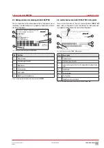
4.3 Position numbers water sampling station
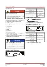
The figure shows a
EASYPRO
4
water sampling station. This version has
the maximum equipment. Your water sampling station may differ in
terms of scope and fittings.
1
2
3
4
5
6
7
8
9
10
11
12
Fig. 2: Water sampling station
EASYPRO 4
No.
Position
1
Multi-channel controller
TOPAX
®
MC
2
Flow control
3
Sample water filter
4
Flow controller
5
Inflow tap
6
Extraction point
7
Measuring point 1 (e. g. disinfection measuring cell)
8
Measuring point 2 (e. g. pH value measuring cell)
9
Measuring point 3 (e. g. redox value measuring cell)
10
Measuring point 4 (e. g. conductivity measuring cell)
11
buffer solutions
12
Outflow tap
Tab. 5: Position numbers water sampling station
EASYPRO 4
4.3.1 Main view
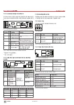
The main menu view will appear upon the start of the product or 5 min-
utes after the last input. The main view shows the current values from up
to four sensors and further information.
2
1
4
5
3
6
Fig. 3: Main view with three sensors
Item
Function
1
Login/password settings
2
Date/time
3
Measured values
4
Main menu
5
File Browser
6
Status row for messages
Tab. 6: Position numbers main view
4.4 The structure of the flow controller
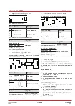
Fig. 4: The structure of the flow controller
Item
Description
1
Outlet connection
2
Inlet connection above (with sealing plugs)
3
Setting screw
4
Fixing screws
5
Inlet connection below
6
Extraction point
7
Temperature measurement point (with sealing plugs)
Tab. 7: Position numbers flow controller
1
2
3
4
5
6
7


