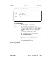
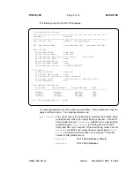


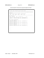


RTRV-T3
4
of
2
Page
RTRV-T3
are:
parameters
output
The
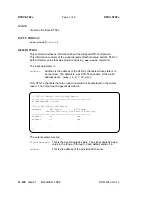
Address
Port
port
DS3
the
of
address
the
is
Address
Port
Mode
DS3
the
of
mode
removal
monitor
violation
the
is
Mode
values:
following
the
of
one
have
may
It
signal.
vmr
errors
P-bit
DS3
remove
and
Monitor
value).
(default
vm
errors.
P-bit
DS3
remove
not
do
but
Monitor
cc
remove
or
monitor
not
Do
channel.
Clear
errors.
P-bit
DS3
BBG20
the
to
apply
not
does
parameter
This
—
pack.
circuit
TMUX
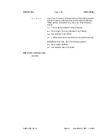
AIS
indication
alarm
DS3
a
not
or
whether
indicates
AIS
be
may
value
The
inserted.
be
should
(AIS)
signal
yes
or
no
BBG20
the
to
applicable
not
is
parameter
This
.
be
will
(—)
dash
a
therefore,
packs,
circuit
TMUX
to
set
is
AIS
When
displayed.
yes
:
upon
DSX-3
the
towards
inserted
is
AIS
DS3
—
path
STS
or
signal
of
loss
OC-N
an
of
detection
fiber.
the
from
incoming
AIS
upon
fiber
the
towards
inserted
is
AIS
DS3
—
DSX-3.
the
from
incoming
LOS
DS3
of
detection
NOTE:
monitor
violation
the
if
inserted
always
is
AIS
for
provisioned
is
mode
removal
vmr
or
vm
.
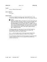
Level
Alarm
DS3
incoming
an
for
level
alarm
the
describes
Alarm
values:
following
the
has
and
failure
signal
CR
alarm
Critical
MJ
alarm
Major
MN
alarm
Minor
NA
alarm
No
alarm
no
reporting
and
for
provisioned
is
system
the
If
user
the
on
LED
ACTY
NE
the
exists,
alarm
an
but
circuit
the
on
LED
fault
the
and
illuminated,
be
will
panel
the
in
reported
be
will
condition
The
flash.
will
pack
Threshold
Failure
a
of
terms
in
threshold
BER
the
is
threshold
Failure
or
-6
either
be
may
value
The
10.
base
the
to
logarithm
10
of
BERs
to
corresponding
-3,
−
6
10
and
−
3
,
respectively.
OC-12
DDM-2000
1997
December
1
Issue
11-213


