


DLP-
550
363-206-295
1997
December
1,
Issue
3
of
2
Page
Procedure
Modification
the
Remove
3.
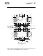
OHCTL and SYSCTL
shelf.
the
from
packs
circuit
connectors
lead
power
shelf
the
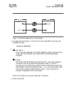
Disconnect
4.
P1 and P2
power
bay
the
from
connectors
riser
J1 and J2
green
The
.
ON
PWR
the
of
front
the
on
LED
extinguish.
gradually
should
panel
user
shelf.
the
in
packs
circuit
remaining
the
Unseat
5.
faceplate.
Panel
User
the
of
bottom
and
top
the
at
screws
the
Remove
6.
Panel.
User
new
the
install
and
out
Panel
User
the
Slide
7.
connector
lead
power
shelf
Reconnect
8.
P1
connector
riser
power
bay
the
to
J1
the
that
verify
and
ON
PWR
lights.
Panel
User
the
on
LED
Completion
and
Verification
connector
lead
power
shelf
Disconnect
9.
P1
lead
power
shelf
Reconnect
.
connector P2
connector
riser
power
bay
to
J2
the
that
verify
and
ON
PWR
lights.
Panel
User
the
on
LED
connector
lead
power
Reconnect
10.
P1
connector
riser
power
bay
to
J1.
the
Install
11.
OHCTL and SYSCTL
shelf.
the
in
packs
circuit
order:
following
the
in
packs
circuit
remaining
the
Reseat
12.
TGS/TG3, TSI,
23G/23G-U or
OLIU
23H/23H-U
, 21G/21G-U/21G2-U or
OLIU
21D/21D-U
,
and 3DS3/3STS1E.
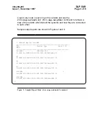
indications.
alarm
of
free
be
should
shelf
the
minutes
10
After
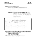
13.
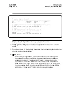
the
Depress
14.
ACO/TST
all
that
verify
and
Panel
User
the
on
pushbutton
the
depress
to
Continue
light.
Panel
User
the
on
LEDs
ACO/TST
shelf
the
in
installed
software
the
of
number
release
the
and
pushbutton
the
in
displayed
be
should
SYSCTL window.


