


DLP-
521
363-206-295
1997
December
2,
Issue
7
of
4
Page
front
the
into
plug
and
port
serial
PC
the
at
connector
the
Remove
4.
Dialup
shelf.
DDM-2000
the
on
port
access
rear
or
modem)
null
(requires
and
A
Tables
ready.
now
is
modem
the
via
element
network
the
to
access
DDM-2000.
the
with
use
for
required
pins
EIA-232-D
the
show
B
Cable
DB-25
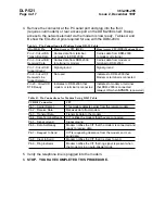
Using
Modem
for
Connections
Pin
A.
Table
Port
Modem
(DTE)
CIT
Access
Rear
(DCE)
CIT
Access
Front
Pin
EIA-232-D
DDM-2000
from
data
Carries
terminal
from
data
Carries
BA
Circuit
-
2
Pin
terminal
or
modem
to
DDM-2000
to
modem
or
Data
Transmitted
or
modem
from
data
Carries
DDM-2000
from
data
Carries
BB
Circuit
-
3
Pin
DDM-2000
to
terminal
modem
or
terminal
to
Data
Received
ground
Signal
ground
Signal
AB
Circuit
-
7
Pin
Ground
Signal
that
DDM-2000
to
Indicates
used
Not
CF
Circuit
-
8
Pin
connected
is
terminal
or
Modem
Line
Received
Detector
Signal
terminal
or
modem
to
Indicates
that
DDM-2000
to
Indicates
CD
Circuit
-
20
Pin
connected
is
DDM-2000
that
connected
is
terminal
or
modem
Ready
DTE
when
ON
(always
SYSCTL
powered)
is
Cable
DB-9
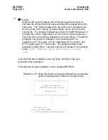
Using
Modem
for
Connections
Pin
B.
Table
CIT
Connector
DB-9
PC
modem.
remote
the
from
carrier
detects
modem
This
Detect
Carrier
-
1
Pin
modem
from
data
Receives
Data
Receive
-
2
Pin
modem
the
to
data
Transmits
Data
Transmit
-
3
Pin
connected
are
they
that
modem
the
notifies
CIT
Ready
Terminal
Data
-
4
Pin
ground
Signal
ground
Signal
-
5
Pin
and
connected
is
modem
the
that
CIT
the
notifies
Modem
Ready
Set
Data
-
6
Pin
data.
receive
to
ready
can
it
so
modem
the
from
clearance
requesting
is
CIT
Send
to
Request
-
7
Pin
data.
send
send.
to
clear
is
it
that
CIT
the
notifies
Modem
Send
to
Clear
-
8
Pin
when
present
is
signal
ring
that
CIT
the
notifies
Modem
indicator
Ring
-
9
Pin
mode.
auto-answer
an
in
is
modem
the
modem.
the
into
plugged
is
line
telephone
the
Verify
5.
6.
PROCEDURE.
THIS
COMPLETED
HAVE
YOU
STOP.


