


363-206-295
Transmission and Synchronization Interfaces
5-14
Issue 1
December 1997
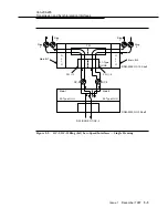
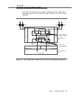
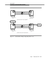
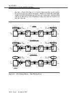
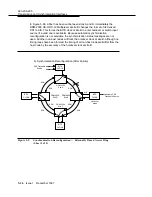
Figure 5-6a shows the CO system is internally timed (free-running). At the remote
terminal (RT), the TG derives its timing from the incoming optical signal and uses
it to time itself and loop timing back to the CO.
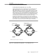
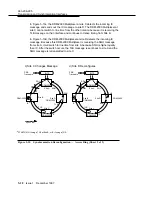
Figure 5-6b and Figure 5-6c show the CO timed from an external stratum 3 or
better source. The RT derives its timing from the incoming optical line and can
send a DS1 output to a BITS clock.
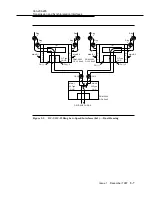
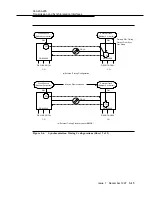
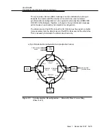
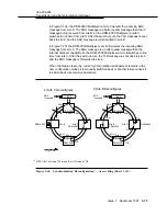
The external timing configuration (Figure 5-6d) uses external DS1 timing to each
DDM-2000 Multiplexer in the network. Since this configuration requires local office
clocks at each site, it is most suited to interoffice applications. A DDM-2000
network may have all DS1 references traceable to a primary reference source
(synchronous operation) or multiple primary reference sources (plesiochronous
operation).
The PRS is equipment that provides a timing signal whose long-term accuracy is
maintained at 10
-11
or better with verification to universal coordinated time (time
and frequency standard maintained by the U. S. National Institute of Standards
and Technology), and whose timing signal is used as the basis of reference for the
control of other clocks in a network.
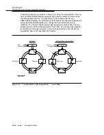
An interoffice ring should have each node externally timed if BITS clocks are
available. All other rings should have one node externally timed (two in some dual
homing configurations) and the rest of the nodes line timed. See 363-206-200,
DDM-2000 Multiplexer Applications, Planning, and Ordering Guide, for more
synchronization information.
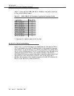
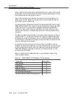
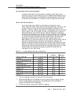
Table 5-2 summarizes the DDM-2000 OC-12 synchronization modes for the
current software release.
Table 5-2.
DDM-2000 OC-12 Multiplexer Synchronization
Application
Ring (R7.0)
Free-Running
X
Line-Timing
X
External Timing
X
DS1 Sync Output
X
Synchronization Messaging
X
Automatic Synchronization Reconfiguration
X


