


363-206-295
DLP-
510
18
of
7
Page
1997
December
1,
Issue
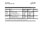
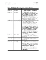
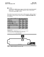
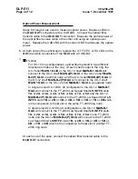
Connector
Edge
S1
OFF
ON
Component Side
4
3
2
1
Switch
Option
TGS
BBF2
2.
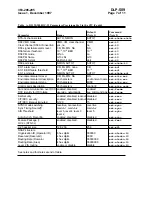
Figure
7.
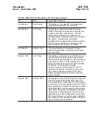
NOTE:
Switches S1-1 and S1-2
the
time
first
the
system
the
by
ignored
are
TGS
to
set
is
mode
timing
the
unless
installed
is
External
DS1
.
the
of
replacement
or
removal
Subsequent
TGS
switches
that
requires
S1-1 and S1-2
update
an
or
settings
original
the
as
same
the
set
be
(
upd
performed.
be
must
command
)
to
set
mode
timing
Is
External
DS1
?
If YES
with
continue
then
,
8.
Step
If NO,
PROCEDURE.
THIS
COMPLETED
HAVE
YOU
STOP.
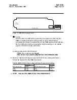
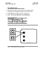
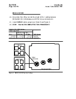
frame
and
coding
line
DS1
the
set
and
2
Figure
and
D
Table
to
Refer
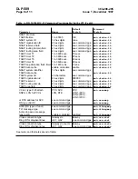
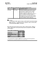
8.
the
for
required
as
format
TGS
pack.
circuit
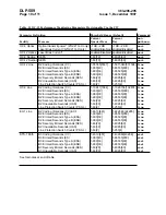
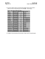
Settings
Switch
Format
Frame
and
Coding
Line
DS1
TGS
BBF2
D.
Table
Switch
Switch
S1-2
Format
Frame
DS1
S1-1
Code
Line
DS1
ON
SF
ON
AMI
OFF
ESF
OFF
B8ZS
9.
PROCEDURE.
THIS
COMPLETED
HAVE
YOU
STOP.


