Eaton MTL831B, Manual
The Eaton MTL831B is a reliable and innovative product designed to enhance your industrial process control. This high-quality manual, available for free download from our website, provides detailed instructions to effortlessly optimize your operations. Unlock the full potential of your MTL831B with our comprehensive user manual.
Share
Download


Reviews:
No comments
Related manuals for MTL831B

DMT-3060
Brand: Monacor Pages: 74

cm-100
Brand: Clas Ohlson Pages: 4

MMD 302
Brand: Bosch Pages: 13

VSS8394/01T
Brand: Bosch Pages: 12

MMD 540H
Brand: Bosch Pages: 53

VSS8394/01T
Brand: Bosch Pages: 178

VC7C1305T
Brand: Bosch Pages: 178

TMX-589
Brand: ES Pages: 23

CDM 85
Brand: Clarke Pages: 12

YSI-ProDSS
Brand: YSI Pages: 8

GMT-19A
Brand: GB Instruments Pages: 11

35632-Series
Brand: Oakton Pages: 35

MM37
Brand: MARTINDALE Pages: 6

CM57
Brand: MARTINDALE Pages: 6
82005
Brand: Craftsman Pages: 22
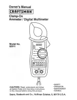
82011
Brand: Craftsman Pages: 12

2020
Brand: Wavetek Pages: 48

HI 9564
Brand: Hanna Instruments Pages: 2


