background image

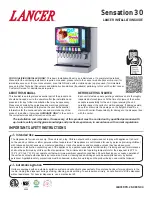
22”, 30” BEVARIETY™ ACIB ICE
BEVERAgE DISPENSERS

MODELS MCY-22 & MCY-30

“Lancer” is the registered trademark of Lancer © 2009 by Lancer, all rights reserved.

LANCER

6655 Lancer Blvd.

San Antonio, Texas 78219

To order parts, call 

Customer Service: 800-729-1500

Warranty/Technical Support: 800-729-1550

Email: [email protected]

www.lancercorp.com

Installation and Service Manual

PN 28-0724/02
6/16/2009

ISO 9001:2000 Quality System Certified

Summary of Contents for BEVARIETY MCY-22

Page 1: ...09 by Lancer all rights reserved LANCER 6655 Lancer Blvd San Antonio Texas 78219 To order parts call Customer Service 800 729 1500 Warranty Technical Support 800 729 1550 Email custserv lancercorp com www lancercorp com Installation and Service Manual PN 28 0724 02 6 16 2009 ISO 9001 2000 Quality System Certified ...

Page 2: ...onents Bag in Box Systems Perform Every Six Months 27 3 Illustrations and Parts Listings 28 3 1 Decals and Labels 28 3 2 Final Assembly Post Mix IBD and Ice Dispenser 30 3 3 22 Bevariety ACIB Faucet Plate and Ice Chute Sub Assembly Post Mix IBD 32 3 4 30 Bevariety ACIB Faucet Plate and Ice Chute Sub Assembly Post Mix IBD 34 3 5 Electrical Box and Gear Motor Sub Assembly Post Mix IBD 36 3 6 Remote ...

Page 3: ...76 6 5 Electronics 78 6 6 General Troubleshooting 79 6 7 Troubleshooting Light Emitting Diodes LEDs 80 6 8 Carbonator Troubleshooting 81 6 9 Electronics Troubleshooting 82 6 10 Ice Delivery System 84 6 11 Ice Board Settings 87 6 12 Auger Motor Removal 87 6 13 Dispenser Connections Valve Map Summary CO2 Water and Syrup 89 6 14 22 Bevariety ACIB Wiring Diagram 115V 60Hz 90 6 15 30 Bevariety ACIB Wir...

Page 4: ...g connections Each dispenser must have a separate electrical circuit Do not use extension cords Do not connect multiple electrical devices on the same outlet ALWAYS disconnect power to the dispenser before attempting any internal maintenance Note the keyswitch does not turn off power to the dispenser It must be physically unplugged Only qualified personnel should service the internal components of...

Page 5: ... carb water capable 44 model is two 22 units joined by a kit with optional MVU Features an optional multi flavor valve unit MVU Capable of serving up to three additional brands on each side of the ice dispenser through the MVU valve Can dispense up to three chilled products 30 only or two chilled and one ambient product on each MVU pad Capable of dispensing flavor shots Replaces the two center LEV...

Page 6: ...tubing Ratio cup MVU syrup separator Sanitizing agent for ice bin Brand decals for LEVs and MVU if applicable 50 ml graduated cylinders for flavor shots MVU option only Pressure gauge to measure CO2 pressure 5 32nds Allen wrench Level Utility Requirements The unit requires each of the following utilities 120 VAC 20 amp dedicated circuits both the pump deck and dispenser 1 2 water supply line at th...

Page 7: ... legs 4 in 102 mm ELECTRICAL 115VAC 60Hz 3 AMPs WEIgHT Without ice 270 lbs 122 kg Shipping 292 lbs 132 kg ICE Capacity 150 lbs 68 kg Dispensable 125 lbs 57 kg FITTINgS Soda inlets 3 8 barb Syrup inlets 3 8 barb WATER Filtered water 50 PSI min 3 52 KG cm2 Min flowing pressure 25 PSIG 1 76 kg cm2 1 72 BAR Max static pressure 50 PSIG 3 52 kg cm2 3 45 BAR CARBON DIOXIDE CO2 Min pressure 70 PSIG 4 92 k...

Page 8: ... mm Optional legs 4 in 102 mm ELECTRICAL 115VAC 60Hz 3 AMPs WEIgHT Without ice 327 lbs 148 kg Shipping 356 lbs 161 kg ICE Capacity 250 lbs 113 6 kg Dispensable 175 lbs 79 5 kg FITTINgS Soda inlets 3 8 barb Syrup inlets 3 8 barb WATER Filtered water 50 PSI min 3 52 KG cm2 Min flowing pressure 25 PSIG 1 76 kg cm2 1 72 BAR Max static pressure 50 PSIG 3 52 kg cm2 3 45 BAR CARBON DIOXIDE CO2 Min pressu...

Page 9: ...2 20 1 31 23 1 2 18 5 8 1 7 8 7 1 2 1 1 2 3 DIAMETER OPTIONAL 3 18 11 7 1 2 2 F R O N T O F D I S P E N S E R OPTIONAL HOLES FOR FASTENING DISPENSER TO COUNTER WITH SCREWS CUT OUT DASHED AREA FRONT OF DISPENSER EXTENDED SPLASH PLATE 1 D R I P T R AY ...

Page 10: ... COUNTER CUTOUT 30 28 1 8 15 16 31 23 1 2 18 5 8 1 5 8 7 1 2 1 1 2 3 DIAMETER OPTIONAL 3 26 15 11 1 2 2 F R O N T O F D I S P E N S E R OPTIONAL HOLES FOR FASTENING DISPENSER TO COUNTER WITH SCREWS CUT OUT DASHED AREA D R I P T R AY ...

Page 11: ...enser AA Number of flavors B Merchandiser graphics designation C MVU option 0 no MVU 2 MVU X Valve flow rate Y Valve Type Z Splash plate type 82 4004 4 Heavy Duty Adjustable Let Kit 4 Legs 82 4054 22 Drip Tray Kit 82 4055 44 Drip Tray Kit 82 4046 30 Drip Tray Kit 82 4007 44 Joining Kit Hardee s 82 3962 44 Joining Kit Carl s Jr KIT PART NUMBERS ...

Page 12: ...NSF standards A backflow prevention device must comply with ASSE and local standards It is the responsibility of the installer to ensure compliance Refer to specific icemaker model for proper air intake exhaust ventilation with Lancer units Install the icemaker per manufacturer specifications Points of consideration include drainage ventilation and drop zones An adapter plate is required when inst...

Page 13: ...INIMUM of 6 152 mm wall clearance MINIMUM of 6 152 mm clearance above ice maker 31 775 mm A I R OUT AIR OUT AIR O U T AIR O U T MINIMUM of 6 152 mm clearance above ice maker 6 152 mm clearance 6 152 mm clearance 30 762 mm Note Please refer to specific icemaker model for proper intake exhaust ventilation with Lancer units 35 5 901 7 mm 31 775 mm ...

Page 14: ...rain spider may become dislodged from its original position Prior to installing the dispenser ensure the drain spider is in the correct position This will prevent drain clog issues Inspect the lower bin area and reach under the shroud to ensure the drain spider is secure in the coldplate cutout If the spider is not in place proceed with the following steps 1 Remove clip 2 and pin 4 from agitator b...

Page 15: ... legs all connections to the inlets on the cold plate will need to have 3 8 90 splices as the beverage tubing will kink if you try to run the tubing directly into the fittings on the cold plate 1 7 CONNECTINg WATER Connect water as follows using 1 2 black line 1 From source to booster if needed 2 From booster to filter 3 From filter to water regulator on pump platform 4 From pump outlet to soda wa...

Page 16: ... of an electrical plug It should be at installed at least six inches off the floor recommend installing on a shelf 3 Connect liquid level control to probe using harness provided Ensure that quick connects are fastened tightly together NOTE Failure to connect pump platform to probe may cause the pump motor to run continuously causing the motor to overheat If this happens unplug unit wait five minut...

Page 17: ...nt of the unit and connect 3 Install shutoff valve in CO2 line prior to CO2 inlet fitting 1 10 CONNECTINg SYRUP LINES 1 Using the illustrations as guides connect syrup lines to appropriate inlets as illustrated beginning with inlet number one on the right side of the dispenser NOTE 1 Refer to project plan for brand line up NOTE 2 90 fittings should be used on all installations where dispenser sits...

Page 18: ...t all configurable valves are set to the correct carb non carb option Refer to section 4 18 for the procedure The configurable valves are valves 2 5 on the 22 without an MVU and valves 3 6 on the 30 without an MVU 1 Install tubular insulation onto the drip tray drain fitting Insulation should sit flush against the back of the drip tray Insulation has a 5 8 ID with a 3 8 wall and is 3 4 thick 2 Ext...

Page 19: ...Keep open until water comes out of relief valve 3 Close relief valve 4 Activate all valves until a flow of plain water is established from each valve 5 Turn on CO2 at source and ensure the high pressure regulator is set at 75 PSIG 6 Empty the carbonator tank by activating a valve until no water comes out 7 Plug in the carbonator pump motor The pump will cycle for 5 5 seconds shut down and start ag...

Page 20: ...g approximately 2 of duct tape on the overlap joint as show Repeat this step for each syrup inlet except the ambient tube inlets 3 Position the Upper CO2 Recess Cover over the relief valve and press into place as show The foam should be flush with the sheet metal mounting plate 4 Place the Probe Nut Insulation on the probe cord Slide the Probe Nut Insulation into the opening of the plastic nut The...

Page 21: ...nst the sheet metal surface 6 Remove the protective backing from the Probe Cord Wrap Place on front of Carbonator Probe Insulation while bending the probe cord down Wrap the middle section of Probe Cord Wrap around the carbonator probe cord 7 Wrap the bottom section around the Carbonator Probe Cord The second picture is a view of the complete Carbonator Probe Cord Insulation ...

Page 22: ...on the bottom side Press into place as shown The foam should be flush with the sheet metal mounting plate 9 Clean area around drain tubes Slightly pinch elbow fitting to form oval 10 Slide elbow fitting over flared end of drain tube Push elbow fitting back over tube until flare reaches angle point ...

Page 23: ... the splash plate drip tray and cup rest 1 13 FINISHINg THE DISPENSER INSTALLATION 1 Connect BIB connectors to BIBs 2 Set the low pressure regulator to 65 PSIG 3 Activate all valves to purge air from the syrup lines 4 Fill unit approximately half full with ice Push chute and check for ice delivery 5 Finish filling unit with ice 6 Install top cover 7 Set ratio for beverage dispensing valves accordi...

Page 24: ...ning and sanitizing should be performed by trained personnel only Use sanitary gloves during cleaning and sanitizing operations Observe applicable safety precautions Follow instruction warnings Do not disconnect water lines when cleaning and sanitizing syrup lines to avoid contamination Do NOT use strong bleaches or detergents They tend to discolor and or corrode various materials Do NOT use metal...

Page 25: ...xtra nozzle Sanitary gloves 2 3 DAILY CLEANINg Using cleaning solution clean top cover and all exterior stainless steel surfaces Clean exterior of dispensing valves and ice chute Remove cup rest Clean drip tray and cup rest and replace cup rest Wipe clean all splash areas using a damp cloth soaked in cleaning solution 1 Carefully remove the nozzle housings by turning counterclockwise and pulling d...

Page 26: ...d pull out of rear bearing to remove 4 Remove dispensing wheel from motor shaft by sliding rearward 5 Remove dispensing wheel shroud 6 Remove splash plate assembly by lifting it up and out from the dispenser face 7 Using cleaning solution described in Section 2 2 and a clean cloth or soft brush clean all removable parts sides of ice bin ice chute and surface of aluminum casting 8 Repeat Step 7 for...

Page 27: ...7 Activate valve to flush and rinse line and fittings for a minimum of sixty seconds to remove all traces of cleaning solution Continue rinsing until testing with phenolpthalein shows that the rinse water is free of residual detergent 8 Following the instructions as described in 2 2 above mix appropriate amount of sanitizing solution in a clean container Place syrup inlet line in container filled ...

Page 28: ...28 28 0724 02 3 Illustrations and Parts Listings 3 1 Decals and Labels 1 1 2 3 4 5 6 6 7 7 ...

Page 29: ...l Cleaning Merchandiser 6 06 3135 Label Wiring Diagram 22 Bevariety ACIB 7 06 3136 Label Plumbing Diagram 22 Bevariety ACIB 30 BEVARIETY ACIB ACIB Item Part No Description 1 06 1139 Label Warning Lid IBD 2 06 2072 Panel Graphic IBD30 Round 3 27 0070 Diffuser Lens IBD30 4 27 0064 Clear Lens IBD30 5 06 1184 Label Cleaning Merchandiser 6 06 3122 Label Wiring Diag 30 Bevariety ACIB 7 06 3123 Label Plu...

Page 30: ...30 28 0724 02 3 2 Final Assembly Post Mix IBD and Ice Dispenser ...

Page 31: ... VC 375 8 14 82 4042 Drip Tray Assy 22 Bevariety ACIB 15 82 4027 Splash Plate Assy Ext Insul 22 16 30 0142 Splash Plate 22 Bevariety ACIB 30 BEVARIETY ACIB ACIB Item Part No Description 1 05 1310 Wheel Shroud IBD30 2 03 0368 Retainer RUE 14 S 3 23 1373 Agitator Assy HEX IBD 115V 4 10 0762 Pin Agitator IBD Single Retainer 5 82 3556 Dispensing Wheel Assy HEX IBD 115V 6 05 2730 Lid Back 30 Bevariety ...

Page 32: ...32 28 0724 02 3 3 22 Bevariety ACIB Faucet Plate and Ice Chute Sub Assembly Post Mix IBD 11 1 1 1 1 2 3 4 6 7 9 9 5 10 12 12 13 14 15 22 27 28 29 30 23 26 34 24 25 31 32 33 21 ...

Page 33: ... 0353 Linkage Door IBD K 04 0320 Screw 8 32 X 0 187 PHD 11 82 1551 Trim Assy 22 IBD 12 30 10174 Faucet Plate MVU 22 13 30 10221 Cover Electrical Housing Ballast 14 82 3965 CO2 Final Assy Bevariety ACIB 30 15 12 0244 Ice Door Switch 16 10 0732 Shaft Ice Chute Door 17 05 0359 Bushing Shaft 18 03 0113 Ring Retaining 5144 12 19 05 0546 Lever Door 20 03 0205 Ring Retaining 5304 25 21 30 10219 Faucet Pl...

Page 34: ...34 28 0724 02 3 4 30 Bevariety ACIB Faucet Plate and Ice Chute Sub Assembly Post Mix IBD 11 26 27 28 14 9 29 12 10 9 1 6 7 1 1 2 30 22 33 24 32 23 31 25 12 13 21 5 4 3 15 ...

Page 35: ...inkage Door IBD K 04 0320 Screw 8 32 X 0 187 PHD 11 82 1618 Trim Assy IBD30 Round 12 30 10132 Faucet Plate MVU 30 Bevariety ACIB 13 30 10221 Cover Electrical Housing Ballast 14 82 3965 CO2 Final Assy Bevariety ACIB 30 15 12 0244 Ice Door Switch 16 10 0732 Shaft Ice Chute Door 17 05 0359 Bushing Shaft 18 03 0113 Ring Retaining 5144 12 19 05 0546 Lever Door 20 03 0205 Ring Retaining 5304 25 21 01 26...

Page 36: ...36 28 0724 02 3 5 Electrical Box and gear Motor Sub Assembly Post Mix IBD 1 2 28 7 20 21 22 25 24 14 13 15 12 11 10 9 6 5 19 4 4 16 4 23 4 17 18 4 3 8 27 ...

Page 37: ...racket Transformer Merc 13 04 0033 Washer FLT 1 4 x 065 x 281 ID x 625 OD 14 04 0726 Scr 1 4 20 x 2 50 HEXHD Zinc 15 04 1552 Screw 10 24 x 1 2 PHD PH 18 8 SS 16 30 10323 Wrapper Ext Right Side Bevariety ACIB 17 30 10218 Wrapper Rear 22 Bevariety ACIB 30 10256 Wrapper Ext Back 30 Merc 18 30 10255 Wrapper Ext Left Side Bevariety ACIB 19 06 1580 Label Patent 20 52 3192 Lead Assy Lamp Black Bevariety ...

Page 38: ...38 28 0724 02 3 6 Remote Pump Assembly 9 19 10 11 5 20 21 14 4 16 13 6 2 15 18 3 7 5 17 8 1 12 20 ...

Page 39: ...solator 1 4 20 7 04 0520 01 Screw 1 4 20 x 500 8 06 0075 1 Nameplate Vinyl 9 06 3087 Label Check Valve 10 07 0582 Clamp Pump Motor SS 11 17 0611 Check Valve Vented 12 18 0310 Regulator Water 13 21 0752 Power Cord 14 30 10368 Bracket Pressure Valve 15 30 10369 Plate Base Pump 16 52 3062 Harness Extension 8 FT 17 82 3808 Enclosure Assy 18 82 3913 Motor Assy Remote 19 86 0001 Pump Procon Brass 20 15 ...

Page 40: ...ing block with water or an FDA approved lubricant 7 If syrup out light is furnished with valve run light wires through mounting block and valve plate Connect wiring to pressure switch in product line 24 VAC power supply required 8 Install mounting block to valve plate using four mounting screws removed from existing mounting block 9 Install valve on mounting block Push wire retainer down This will...

Page 41: ...ate valve to fill separator syrup tube 6 Hold a Lancer Brix cup under syrup separator Dispense water and syrup into cup for two seconds Divide number of ounces ml of water in cup by two to determine water flow rate per second 7 To obtain desired water flow rate use a screwdriver to adjust water flow control 4 5 ADJUSTINg WATER TO SYRUP BRIX For the Model 100 the syrup flow may be adjusted from 0 2...

Page 42: ...emove diffuser by pulling down 9 Hold cup lever back and lay soda lever across bottom of valve with small leg extending through hole Twist soda lever slightly and bring to upright position Soda lever will slide between the vertical supports 10 Release cup lever 11 Line up holes in supports and soda lever and install stainless steel pin 12 Install diffuser and nozzle 13 Install valve on mounting bl...

Page 43: ...at the contact pad faces towards the rear of the valve a Insert the front soda water lever through the bottom plate and rotate the lever to the left until the contact pad is facing forward and the extension is positioned over the paddle arm on the left b To install spring press stud pin into hole on upper body and fit one end of spring into outer groove of stud pin Fit other end of spring into hol...

Page 44: ...to sleeve c Turn clockwise to tighten bushing inside sleeve NOTE This will allow sleeve to be removed or installed d Turn counterclockwise to loosen bushing inside sleeve This will allow tool to be removed from sleeve 11 To replace sleeve place sleeve on flow control extractor tool and insert in upper body 12 Lubricate o ring with water or any FDA approved lubricant and push sleeve to bottom 13 Re...

Page 45: ... the instructions of the dispenser manufacturer to properly clean and sanitize the nozzle and diffuser and ensure no off taste is present 4 10 BI WEEKLY SANITIZINg Nozzle and diffuser must be sanitized bi weekly Comply with the instructions of the dispenser manufacturer to properly sanitize the nozzle and diffuser and ensure no off taste is present 4 11 SYRUP RATIO CUP 05 1436 Ratio Cup 4 75 5 25 ...

Page 46: ...4 Insufficient water flow 1 Water flow pressure is too low or restricted 2 Foreign debris in water flow controls 1 Check incoming water from carbonator to ensure minimum flowing pressure See specifications Check stems on mounting block to ensure it is in fully OPEN position 2 Remove water flow control from upper body and clean out any foreign materials to ensure smooth free piston movement 5 Insuf...

Page 47: ... mounting block to ensure they are in fully OPEN position 2 If not repair or replace 3 Check electric current supplied to valve See specifications If current is adequate check solenoid coil and switch Replace if necessary 4 Remove valve from mounting block and open stems slightly Check to ensure proper water and syrup supply If no supply check dispenser for freeze up or other problems 5 Check manu...

Page 48: ...fective solenoid armature or spring 4 Remove debris and or replace damaged paddle arms 10 Excessive foaming 1 Incoming water or syrup temperature too high 2 Water flow rate too high 3 Nozzle and diffuser not clean 4 Nozzle and diffuser not properly installed 5 CO2 pressure too high 1 Correct at dispenser 2 Re adjust and reset Brix 3 Remove and clean 4 Remove and install properly 5 Check for proper...

Page 49: ...49 28 0724 02 Notes ...

Page 50: ... 20 16 21 22 23 24 25 16 16 12 13 11 14 15 19 16 21 22 23 24 25 43 17 42 41 1a 1 2 44 48 11 Syrup Out Light Kit Option PN 82 0783 Front Soda Water Lever Kit PN 82 1458 Flow Control 3 0 Syrup Kit PN 82 1027 Flow Control 4 5 Syrup Kit PN 82 2226 Flow Control 3 0 Soda Kit PN 82 1026 Flow Control 4 5 Soda Kit PN 82 2227 53 51 52 Nozzle Assembly 4 5 Kit PN 82 2014 ...

Page 51: ... Item No 16 21 23 24 03 0088 Retainer Flow Control 25 04 0267 Screw 26 82 2929 Arm Paddle Assy 27 54 0046 Body Assy Lower 3 0 54 0188 Body Assy Lower 4 5 28 02 0408 O Ring Nozzle Red 3 0 Used in Valves produced through September 1998 29 05 0232 Plate Bottom 3 0 05 1108 Plate Bottom 4 5 30 04 0310 Screw 31 02 0133 O Ring Used in Valves produced through September 1998 32 05 0281 Plug Bottom Plate 33...

Page 52: ...5 37 10 22 35 8 9 6 40 39 7 5 3 4 38 19 41 42 U S H P 45 36 1a 47 48 17a Syrup Out Light Kit Option PN 82 0783 29 11 31 34 33 32 30 46 44 50 49 Flow Control 3 0 Syrup Kit PN 82 1027 Flow Control 4 5 Syrup Kit PN 82 2226 Flow Control 3 0 Soda Kit PN 82 1026 Flow Control 4 5 Soda Kit PN 82 2227 Front Soda Water Lever Kit PN 82 1458 51 Nozzle Assembly 4 5 Kit PN 82 2014 52 53 16 ...

Page 53: ...ustment Assy White Item No 16 21 23 24 03 0088 Retainer Flow Control 25 04 0267 Screw 26 82 2929 Arm Paddle Assy 27 54 0046 Body Assy Lower 3 0 54 0188 Body Assy Lower 4 5 28 02 0408 O Ring Nozzle Red 3 0 Used in Valves produced through September 1998 29 05 0232 Plate Bottom 3 0 05 1108 Plate Bottom 4 5 30 04 0310 Screw 31 02 0133 O Ring Used in Valves produced through September 1998 32 05 0281 Pl...

Page 54: ...Light Kit Option PN 82 0783 17 35 14 18 20 16 21 22 23 24 25 28 27 26 40a 43 42 41 PUSH 45 10 30 11 31 34 32 29 33 46 44 48 47 Front Soda Water Lever Kit PN 82 1458 Flow Control 3 0 Syrup Kit PN 82 1027 Flow Control 4 5 Syrup Kit PN 82 2226 Flow Control 3 0 Soda Kit PN 82 1026 Flow Control 4 5 Soda Kit PN 82 2227 1 2 16 Nozzle Assembly Kit 4 5 PN 82 2014 49 50 51 ...

Page 55: ...4 03 0088 Retainer Flow Control 25 04 0267 Screw 26 82 2929 Arm Paddle Assy 27 54 0046 Body Assy Lower 3 0 54 0188 Body Assy Lower 4 5 28 02 0408 O Ring Nozzle Red 3 0 Used in Valves produced through September 1998 29 05 0232 Plate Bottom 3 0 05 1108 Plate Bottom 4 5 30 04 0310 Screw 31 02 0133 O Ring Used in Valves produced through September 1998 32 05 0281 Plug Bottom Plate 33 04 0775 Pin Lever ...

Page 56: ...nections The 22 inch unit is very similar to the 30 inch model 4 LEV s are installed Positions 2 and 5 have the switchable converters installed behind the backblock Should be set according to the project plan Certain customers will only use the top two pushbuttons on each side of the MVU 10 total connection lines at the bottom of the dispenser 2 inlets are for ambient products only Bottom left sid...

Page 57: ...inserting it into the dispenser The illustrations show both positions of the converter NOTE You must shut down both still and sparkling water supplies as well as the CO2 line and syrup supply to change out the switchable backblock To change from plain to soda 1 Shut off water Syrup and CO2 2 Gas out dispenser 3 Remove backblock 4 Pry converter out with a small screwdriver as shown 5 Reinstall conv...

Page 58: ...oard activates the syrup and water modules dispensing a drink at the nozzle Note For a flavor shot the board only activates the syrup module Beverages are dispensed either by standard LEV s or by Multi Valve Units The MVU consists of a touch pad that activates Flavor shots Carbonated or non carbonated drinks Portion controlled dispensing for crew serve PC board operates on DC voltage 24 VDC and co...

Page 59: ... Soda or Plain Water 1 Press both top and bottom PUSH buttons at the same time on the MVU panel for 5 seconds On some dispensers the top button may be hidden no PUSH label present In this case the button can be used to enter the programming mode and the button should be set to No Water Light Off The light for the top hidden button will be visible when lit Lights on Plain Water Lights flashing slow...

Page 60: ... Serve If equipped with Portion Controls only three options are available Light on Plain Water Mode Light flashing Soda Water Mode Light off Flavor Shot Mode 3 Press the same brand button again to change to a carbonated beverage light will flash slowly 4 Press the button one more time to change to flavor shot mode a The light will flash quickly and the water will be turned off 5 Repeat this proces...

Page 61: ...mes Press the Shot button a The Shot button will illuminate b Brands enabled for shots will be illuminated 3 Press the Brand button to turn the shot mode for that brand on or off 4 Press the Save Pour cancel button Note If no entries are made for 60 seconds while in programming mode the PC board automatically saves the last changes to the programming however you can exit programming mode sooner by...

Page 62: ... the same time approximately 5 seconds a The pour cancel button will illuminate and the shot LED will blink 5 times b The Self Serve format uses the same two buttons to check flow rate 2 Place a ratio cup under the nozzle and press a brand button Water will pour for 4 seconds 3 Check for 10 oz of water in the ration cup 3 0 LEV If above or below 10 oz adjust the water soda flow control and recheck...

Page 63: ...all chamber 3 Push a brand button and fill the cup up to the appropriate syrup window If the ratio levels are correct move to the next brand If levels are incorrect adjust the flow controls To ratio the MVU Crew Serve 1 Attach the syrup separator and activate the valve to load the separator with syrup 2 Position the ratio cup as shown The arm of the separator must be aimed at the large chamber The...

Page 64: ...ight will illuminate and the shot light will blink 2 times 2 Press the brand button The selected brand s LED will illuminate Multiple brands can be set at the same time Example Choose buttons 5 and 11 The first button illuminated will stay on and that brand will pour The second button will flash indicating that the portion will be set for that brand as well Note The LED will blink twice and turn o...

Page 65: ...programming mode Note The most recent programming entries will be saved automatically after 60 seconds if no other buttons are pressed Check Adjust Flavor Shots Self Serve Flavor shots should be adjusted so that approximately ten ml of syrup pours each time the button is pushed To check dispensed amount 1 Use a 50 ml graduated cylinder 2 Place the graduated cylinder under the nozzle 3 Press the Fl...

Page 66: ...and button to activate for shot mode The brand button will illuminate Note If brand is not enabled for shot mode the LED light will blink twice and turn off 4 Place a 50 ml graduated cylinder under the nozzle 5 Press and hold XL portion button until the portion size is achieved Target is 30 ml 1 oz of syrup for an XL portion Repeat steps 2 through 4 for each of the other brands Note The other size...

Page 67: ...e branded flavor shot 10 ml will pour from the nozzle Press button again to add additional shot Beverage Dispensing 1 Place cup under MVU nozzle 2 Press and hold the PUSH button for the brand until the cup is filled The beverage continues to pour until the button is released Note If the button is pressed continuously it will time out and stop pouring after ten seconds ...

Page 68: ...and button Button stays active for 10 seconds Press again to deactivate 3 Press portion size button to dispense flavor shot Press Pour Cancel to stop dispense mode Dispense Beverage 1 Press the brand button Button stays active for 10 seconds or until another brand is pressed 2 Press a portion control size button Beverage will pour Note Press a brand then pour cancel to manually dispense a beverage...

Page 69: ...69 28 0724 02 Notes ...

Page 70: ...70 28 0724 02 5 3 MVU Assembly 3 4 5 6 7 8 9 10 11 12 13 14 5 ...

Page 71: ...375 8 05 2699 Nozzle Outer 9 05 2713 Bracket Nozzle Left or 05 2714 Bracket Nozzle Right 10 03 0233 Retainer LEV 11 49 0319 Sub Assy Nozzle MVU 12 64 5011 PCB Assy MVU Controller 13 30 10200 Electrical Housing Bevariety ACIB 14 30 10202 Cover Electrical Housing 15 06 3094 Crew Serve 3 Flavor 06 3095 Crew Serve 3 Flavor No Water 06 3096 Self Serve 3 Flavor 06 3097 Self Serve 3 Flavor No Water 06 31...

Page 72: ...V 3 0 4 5 Syrup Assy 82 3824 LFCV 3 0 4 5 Soda Water Assy LFCV Spare Parts 1 10 0430 05 Plug Nut 2 02 0538 O Ring 3 12 0364 04 01 Coil LFCV 4 23 1301 01 Core Seal Assy 5 03 0180 02 Spring Core 6 02 0109 O Ring 7 05 1745 02 Seat LFCV 8 02 0133 O Ring LFCV Kit 82 4020 LFCV Rebuild Kit 8 7 5 4 3 2 Spare Parts Valve Assembly 1 6 ...

Page 73: ...p Multiflavor Nozzle Vinyl 1 x 206 4 07 0446 Clamp Stpls Oetkr 5 08 0105 Tubing B44 4x 1 4 ID X 063 Wall 6 07 0437 Clamp Stpls Otkr 7 01 2126 U Bend SS 1 4 Barb 8 05 1866 Elbow 5 Dole X 25 Barb Pls 9 02 0089 O Ring 2 012 97 0999 10 05 1385 Elbow 5 Dole X 2 11 07 0443 Clamp Stpls Oetkr 12 08 0391 Tubing B44 4x 187 ID X 312 OD 1 2 3 3 4 5 6 6 5 4 8 9 11 10 9 12 7 ...

Page 74: ...ir the ice In addition the auger pushes ice to the cold plate and also to the dispense chute where it is directed into drinks Note The only ice recommended is cube ice from an ice machine The ice used should be approximately 32 F Types of ice to avoid Crushed ice Pellets Melts too quickly Freezer ice Can freeze both water and diet syrups Can damage the auger and motor as well ...

Page 75: ...ed on the pump platform pumps pressurized water to the cold plate The pump assembly consists of the following items Pump Motor Liquid level control Water pressure regulator The water is chilled in the cold plate prior to entering the picture frame carbonator tank It is sprayed atomized into the carbonator tank through a small orifice where it absorbs CO2 and becomes soda water Note A water booster...

Page 76: ...icture Frame Carbonator Tank embedded in cold plate 131 oz capacity CO2 Check Valve Prevents carbonated water from backing into the CO2 system Backflow Preventor Prevents carbonated water from backing into building s water supply Relief Valve Vents the carbonator when pressure exceeds 240 psig Carbonator Pump Consists of the following components Pump Motor Standard 1 3 hp motor Water Pump Standard...

Page 77: ...water regulator restricts the incoming water pressure to 50 psig for water entering the carbonator tank Since the CO2 pressure is set to 75 psig this creates more than enough pressure difference between the water and CO2 gas to create soda water ...

Page 78: ...rced from a terminal strip for both the transformer and the Ice Board The Ice Board uses 120 VAC to power the auger motor The ice board also converts 24 VAC from the transformer rectifies to DC for use with the ice gate solenoid and switch The MVU board controls all beverage dispensing functions It receives 24 VAC from the transformer and rectifies it to 24 VDC to operate the MVU dispensing valves...

Page 79: ... in 2 PC board malfunctioning 3 Motor malfunctioning 1 Plug in wiring harness 2 Replace PC board 3 Replace motor 3 Push chute motor runs but trap door does not open 1 Solenoid not connected to PC board 2 Solenoid malfunctioning 1 Tighten appropriate retaining screws 2 Replace appropriate o rings 4 Push chute trap door opens motor runs but no ice dispenses 1 Dispenser is out of ice 2 Agitator pin i...

Page 80: ... the transformer has tripped If it has tripped it can be reset by depressing the switch on the top of the transformer 4 LED D6 This light is on when 32VDC is present at the circuit board It should be lit whenever the unit is connected to a power source If the light is off check to see if the internal circuit breaker on the transformer has tripped If it has tripped it can be reset by depressing the...

Page 81: ...nator cycles on and off continuously in five second intervals and times out after 30 continuous cycles Unplug probe cable from LLC cable and jumper the green and black wires with a conductor on the LLC side of the probe cable and plug in motor If motor runs inspect probe cable at LLC to ensure proper connection Replace LLC if Black and Green wires are properly connected If motor doesn t run ensure...

Page 82: ...motor Check pressure at pump platform regulator outlet replace regulator if over 50 psig Pump runs and times out after 30 cycles Probe is malfunctioning Unplug probe Pump motor should run If it does replace probe If it doesn t run replace liquid level control Issue Possible Cause Resolution No syrup or water on either MVU No power to MVU board Malfunctioning MVU board Check for lights on the MVU a...

Page 83: ...y dispensing on MVU No water to MVU but water pouring at LEVs Check for 24 VDC at water solenoid If 24 VDC present repair solenoid assembly If 24 VDC no present troubleshoot board and wiring harness Portion control board not working MVU dip switch in wrong position Set switches to correct position ...

Page 84: ...m included in this manual also affixed to the electrical box cover the automatic agitation timing can be changed as follows A set of DIP switches is provided to control the timing and low ice control 1 DIP 3 4 These switches control the ON time for automatic agitation By referring to the table and setting the switches as shown ON times from one second to four seconds in one second increments can b...

Page 85: ... be in the OFF position The unit is shipped with 60 minute OFF time To turn the agitation completely off set switches 5 through 8 all OFF The Ice board can be set to operate the auger motor up to four seconds agitation time with intervals from ten minutes up to every 150 minutes It comes pre set from the factory with one two second rotation every 60 minutes The switch codes on the PC board are as ...

Page 86: ...86 28 0724 02 ...

Page 87: ...late two screws 8 Disconnect wire harness from auger motor 9 Remove auger motor retaining bracket four screws 10 Pull out motor gear box Reverse the steps to install a new motor gear box Note When reinstalling the motor be sure to lock the rue pin see diagram at right and ensure that the shaft seal is in place Lock by moving bent end to opposite side of straight end When locked clip will appear as...

Page 88: ... cover plate 6 Unplug the agitator motor wiring harness 7 Use a Phillips screwdriver to remove the screws from the auger motor retaining bracket 8 Remove the snap ring securing the motor to the auger shaft using a snap ring pliers 9 Pull motor out 10 Insert new auger motor and install new snap ring using snap ring pliers 11 Reinstall retaining bracket plug in motor install cover plate splash plate...

Page 89: ...89 28 0724 02 6 13 Dispenser Connections Valve Map Summary CO2 Water and Syrup ...

Page 90: ......

Page 91: ......

Page 92: ...92 28 0724 02 6 16 22 Bevariety ACIB Wiring Plumbing Diagram 115V 60Hz ...

Page 93: ...93 28 0724 02 6 17 30 Bevariety ACIB Wiring Plumbing Diagram 115V 60Hz ...

Page 94: ...LANCER To order parts call Customer Service 800 729 1500 Warranty Technical Support 800 729 1550 Email custserv lancercorp com www lancercorp com ...

Reviews: