background image

ME8200DTN, WSM

GENERAL

NG-3

A

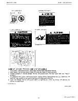
Engine Oil : Oil used in the engine should have an American Petroleum Institute (API) service
classification and Proper SAE Engine Oil according to the ambient temperature as shown above. 
Do not mix different brands together.

A

Transmission Oil : The oil used to lubricate the transmission is also used as hydraulic fluid.  To insure
proper operation of the hydraulic system and complete lubrication of the transmission, it is important
that a multi-grade transmission fluid be used in this system.  We recommend the use of KUBOTA SUPER
UDT fluid for optimum protection and performance. 
Do not mix different brands together.

A

Indicated capacity of water and oil are manufacture's estimate.

0000003594E

KiSC issued 04, 2006 A

Summary of Contents for ME8200DTN

Page 1: ...WORKSHOP MANUAL TRACTOR ME8200DTN SUPPLEMENT KiSC issued 04 2006 A...

Page 2: ...s part should be understood before proceeding with troubleshooting disassembling and servicing For ME8200DTN tractor there are troubleshooting servicing specification lists checking and adjusting disa...

Page 3: ...positions A Never start the engine while standing on ground Start the engine only from operator s seat This symbol the industry s Safety Alert Symbol is used throughout this manual and on labels on th...

Page 4: ...ping Otherwise hot water will spout out from radiator Only remove radiator cap when cool enough to touch with bare hands Slowly loosen the cap to first stop to relieve pressure before removing complet...

Page 5: ...m eyes hands and clothing If you spill electrolyte on yourself flush with water and get medical attention immediately DISPOSE OF FLUIDS PROPERLY A Do not pour fluids into the ground down a drain or in...

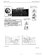
Page 6: ...S N4 The following safety decals are installed on the machine If a decal becomes damaged illegible or is not on the machine replace it The decal part number is listed in the parts list SAFETY DECALS 0...

Page 7: ...ME8200DTN WSM SAFETY INSTRUCTIONS N5 0000003126E KiSC issued 04 2006 A...

Page 8: ...ME8200DTN WSM SAFETY INSTRUCTIONS N6 0000003588E KiSC issued 04 2006 A...

Page 9: ...ME8200DTN WSM SAFETY INSTRUCTIONS N7 0000003589E KiSC issued 04 2006 A...

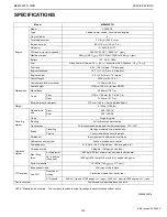
Page 10: ...m Standard tire size Front 280 70R18 Rear 380 70R28 Clutch Single dry plate Steering Full hydraulic power steering Transmission Fully synchronized main and shuttle transmission 12F 12R Brake Travellin...

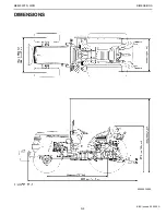
Page 11: ...ME8200DTN WSM DIMENSIONS N9 DIMENSIONS 0000003590E KiSC issued 04 2006 A...

Page 12: ...NG GENERAL KiSC issued 04 2006 A...

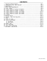
Page 13: ...9 4 CHECK POINTS OF EVERY 100 HOURS NG 10 5 CHECK POINTS OF EVERY 300 HOURS NG 11 6 CHECK POINTS OF EVERY 600 HOURS NG 11 7 OTHERS NG 11 5 SPECIAL TOOLS NG 13 1 SPECIAL TOOL FOR TRACTOR NG 13 6 TIRES...

Page 14: ...CATION When contacting your local KUBOTA distributor always specify engine serial number tractor serial number and hour meter reading 1 Tractor Identification Plate 3 Engine Serial Number 2 Tractor Se...

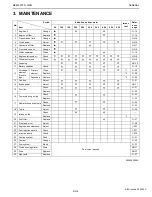
Page 15: ...9 4 lmp qts Engine oil API service classification CD CE or CF Below 0 32 SAE10W 10W 30 or 10W 40 0 to 25 32 to 77 SAE20 10W 30 or 10W 40 Above 25 77 SAE30 10W 30 or 10W 40 4 Transmission case 33 L 34...

Page 16: ...he oil used to lubricate the transmission is also used as hydraulic fluid To insure proper operation of the hydraulic system and complete lubrication of the transmission it is important that a multi g...

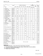
Page 17: ...type Primary element Clean 1 G 20 Replace 2 G 29 Secondary Replace 2 G 29 13 Fan belt Adjust G 21 14 Brake pedal Adjust NG 11 15 Fuel line Check G 21 Replace G 32 16 Power steering oil line Check G 2...

Page 18: ...djust NG 11 15 Fuel line Check G 21 Replace G 32 16 Power steering oil line Check G 24 Replace G 32 17 Radiator hose and clamp Check G 24 Replace G 32 18 Toe in Adjust G 25 19 Intake air line Check Re...

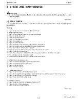
Page 19: ...screen and grill 10 Check the dust and chaff accumulated between the battery and radiator 11 Check the nuts of tires are tight 12 Check the number plate or SMV emblem for damage and replace as necess...

Page 20: ...ew filters 6 Tighten the filter quickly until it contacts the mounting surface Tighten filter by hand and additional 1 2 turn only 7 After the new filter has been replaced fill with the oil up to the...

Page 21: ...lock nut 1 and turn the turnbuckle 2 to adjust the clutch rod length 4 Retighten the lock nut 1 Changing Front Axle Case Oil 1 To drain the used oil remove the right and left drain plugs 2 and fillin...

Page 22: ...s the clutch pedal fully 4 Shift the shuttle shift lever to the neutral position 5 Pull out the engine emergency stop knob and turn the key to START position 6 The engine must not crank 7 If it cranks...

Page 23: ...operated the machine in extremely wet and muddy condition lubricate grease fittings more often 1 Grease Fitting Front Wheel 5 Battery Terminal Case Support RH LH 6 Grease Fitting Top Link 2 Grease Fi...

Page 24: ...CHECK POINTS OF EVERY 300 HOURS Replacing Hydraulic Oil Filter 1 See page NG 7 6 CHECK POINTS OF EVERY 600 HOURS Changing Transmission Fluid 1 See page NG 8 Changing Front Axle Case Oil 1 See page NG...

Page 25: ...a blown fuse determine why the fuse blew and make any necessary repairs Failure to follow this procedure may result in serious damage to the tractor electrical system Refer to troubleshooting section...

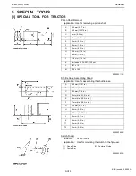
Page 26: ...8 in C 6 mm 0 24 in D 90 mm 3 54 in E 10 mm 0 39 in F 40 mm 1 57 in G 10 mm 0 39 in H 35 6 mm 1 40 in I 36 mm 1 42 in J 41 6 mm 1 64 in K Part code No 3A201 4130 nut L M27 x 1 5 M M10 x 1 25 000000311...

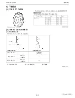
Page 27: ...EAD ADJUSTMENT 1 Front Wheel Front tread width can not be adjusted Type of Tire Front Rear Farm Tire 280 70R18 380 70R28 280 70R18 360 70R28 250 80 18 380 70R28 250 80 16 380 70R24 0000003610E 250 80...

Page 28: ...stability A Always attach tires as shown in the drawings above A If not attached as illustrated transmission parts may be damaged A Do not use tires larger than specified A When re fitting or adjustin...

Page 29: ...sing a front loader of when equipped with lots of front weight Front wheel hub Rear wheel hub Screw circle diameter A 152 4 mm 6 in 203 2 mm 8 in Number of screws 6 8 Screws M14 x P1 5 M16 x P1 5 Hub...

Page 30: ...a tire A Do not fill the front tires with liquid A Refer to ME8200 ME9000 Workshop Manual for liquid and injection method Tire sizes 380 70R24 360 70R28 380 70RE28 Slush free at 24 11 Solid at 46 51...

Page 31: ...mproper implements are not covered by the warranty Tread max width Lower link end max loading weight W0 Front Rear 1110 mm 43 7 in 1440 mm 56 7 in 1900 kg 4190 lbs Actual figures Implement weight W1 a...

Page 32: ...gals 4 Rotary Tiller Max Tilling Width 2130 mm 84 in Max Weight 800 kg 1760 lbs 5 Bottom Plow Max Size 14 in x 3 16 in x 2 18 in x 1 Max Weight 450 kg 1000 lbs 6 Disc harrow 3P Type Max Size 18 in x...

Page 33: ...N1 ENGINE KiSC issued 04 2006 A...

Page 34: ...CONTENTS 1 TIGHTENING TORQUES N1 S1 2 CHECKING DISASSEMBLING AND ASSEMBLING N1 S2 1 SEPARATING ENGINE FROM TRACTOR N1 S2 KiSC issued 04 2006 A...

Page 35: ...5 0 21 7 to 36 2 Power steering hoses retaining nut 24 5 to 29 4 2 5 to 3 0 18 1 to 21 7 Front axle support mounting screw 167 to 196 17 0 to 20 0 123 to 144 Starter s terminal B mounting nut 8 8 to...

Page 36: ...einstall the radiator hose Draining Engine Oil 1 Start and warm up the engine for approx 5 minutes 2 Place an oil pan underneath the engine 3 Remove the drain plugs 1 to drain oil 4 After draining scr...

Page 37: ...rands fluid together Foldable ROPS 1 Disconnect the 2P connector from the front combination lamp 2 2 Remove the foldable ROPS 1 3 Remove the ROPS frame right and left 3 When reassembling Bonnet and Co...

Page 38: ...hose 5 4 Remove the delivery pipe clamp 5 Remove the muffler 1 Power Steering Hoses 1 Disconnect the power steering hoses 1 2 When reassembling 1 Muffler 4 Radiator Hose 2 Radiator Hose 5 Radiator Ho...

Page 39: ...gure Wiring Harness L H 1 Disconnect the battery positive cable 1 2 Disconnect the head light cable 2 and 4WD Bi speed turn connectors 4 3 Remove the hose clamps 3 1 O ring 11 O ring 2 Screw 12 Cover...

Page 40: ...4WD Bi speed switch connector 12 and 4WD indicator connector 13 7 Disconnect the engine stop cable 7 at the engine side 8 Remove the rear bonnet 10 and lower cover 11 Piping for 3 Point Hydraulic Sys...

Page 41: ...A Apply molybdenum disulphide Three Bond 1901 or equivalent to the splines of clutch disc boss A Apply liquid gasket Three Bond 1141 1211 or equivalent to joint face of the engine and clutch housing 1...

Page 42: ...N2 CLUTCH KiSC issued 04 2006 A...

Page 43: ...CONTENTS 1 TRAVELLING CLUTCH N2 M1 KiSC issued 04 2006 A...

Page 44: ...single plate clutch for travelling system 1 Flywheel 8 Gear Shaft 2 Pressure Plate 9 Release Fork 3 Clutch Cover 10 Clutch Disc 4 Diaphragm Spring 11 Clutch Lever 5 Pressure Plate Assembly 12 Clutch...

Page 45: ...ERVICING SPECIFICATIONS N2 S2 3 TIGHTENING TORQUES N2 S3 4 CHECKING DISASSEMBLING AND SERVICING N2 S4 1 TRAVELLING CLUTCH N2 S4 1 Checking and Adjusting N2 S4 2 Disassembling and Assembling N2 S4 3 Se...

Page 46: ...Replace N2 S11 A Wire ring of the pressure plate worn or broken Replace Pressure plate assembly N2 S11 Chattering A Grease or oil on clutch disc facing Replace N2 S10 A Clutch disc or pressure plate...

Page 47: ...Clearance 0 025 to 0 185 mm 0 00098 to 0 00728 in 1 00 mm 0 0394 in Clutch Pedal Shaft O D 27 900 to 27 975 mm 1 09842 to 1 10138 in Clutch Pedal Bushing I D 28 000 to 28 085 mm 1 10236 to 1 10571 in...

Page 48: ...9 4 2 5 to 3 0 18 7 to 21 7 Starter s terminal B mounting nut 8 8 to 11 8 0 9 to 1 2 6 5 to 8 7 Bonnet support mounting screw 48 1 to 55 8 4 9 to 5 7 35 5 to 41 2 Support frame mounting screw 48 1 to...

Page 49: ...tighten the lock nut 3 firmly 2 Disassembling and Assembling Foldable ROPS 1 Disconnect the 2P connector from the front combination lamp 2 2 Remove the foldable ROPS 1 3 Remove the ROPS frame right a...

Page 50: ...eaner hose 3 from the intake manifold 3 Disconnect the radiator hose 5 4 Remove the delivery pipe clamp 5 Remove the muffler 1 Power Steering Hoses 1 Disconnect the power steering hoses 1 2 When reass...

Page 51: ...gure Wiring Harness L H 1 Disconnect the battery positive cable 1 2 Disconnect the head light cable 2 and 4WD Bi speed turn connectors 4 3 Remove the hose clamps 3 1 O ring 11 O ring 2 Screw 12 Cover...

Page 52: ...1 2 Remove the suction pipe 3 3 Remove the delivery pipe 4 for 3 point hydraulic system 4 Remove the delivery pipe 2 for power steering Wiring Harness R H and Fuel Pipes 1 Disconnect the 3P connector...

Page 53: ...ss A Apply liquid gasket Three Bond 1141 1211 or equivalent to joint face of the engine and clutch housing Tightening torque Starter s terminal B mounting nut 8 8 to 11 8 0 9 to 1 2 6 5 to 8 7 ft lbs...

Page 54: ...ing 2 as a unit 2 Remove the release fork setting screws 1 3 Draw out the clutch lever 4 to remove the release fork 3 When reassembling A Make sure the direction of the release fork 3 is correct A Inj...

Page 55: ...ess bearing outer race when replacing release bearing A Do not wash the release bearing with a cleaning solvent Clutch Disc Wear 1 Measure the depth from clutch disc surface to the top of rivet at lea...

Page 56: ...s these parts are invisible from outside shake pressure plate assembly up and down to listen for chattering noise or lightly hammer on rivets for a slightly cracked noise Any of these noises indicates...

Page 57: ...N3 TRANSMISSION KiSC issued 04 2006 A...

Page 58: ...IN FOR TRAVELLING GEAR N3 M2 1 SHUTTLE SHIFT SECTION N3 M2 2 MAIN GEAR SHIFT SECTION N3 M2 3 AUXILIARY GEAR SHIFT SECTION N3 M3 4 4WD BI SPEED TURN SECTION N3 M4 3 POWER TRAIN FOR PTO SYSTEM N3 M5 1 P...

Page 59: ...RANSMISSION 1 TRANSMISSION 1 Shuttle Shift Section Forward Reverse 2 Main Gear Shift Section 3 Auxiliary Gear Shift Section 4 PTO Clutch Section 5 4WD Bi speed Turn Section 6 PTO Gear Shift Section 3T...

Page 60: ...AR 1 SHUTTLE SHIFT SECTION 2 MAIN GEAR SHIFT SECTION 1 Input Shaft F Forward 2 1st Shaft R Reverse 3 Hub 4 Shifter 0000003446E 1 1st Shaft 1 1st Speed 2 Hub 2 2nd Speed 3 Shifter 3 3rd Speed 4 Shifter...

Page 61: ...ME8200DTN WSM TRANSMISSION N3 M3 3 AUXILIARY GEAR SHIFT SECTION 1 2nd Shaft H High 2 Shifter L Low 3 Hub C Creep 4 3rd Shaft 5 Shifter 6 Hub 0000003449E KiSC issued 04 2006 A...

Page 62: ...switch perceives the angle of the front wheel and it becomes bi speed turn drive in 34 degrees or more B 2 Wheel Drive When the 4WD bi speed button is not pushed the hydraulic clutch does not engage...

Page 63: ...YSTEM 1 PTO CLUTCH SECTION 2 PTO GEAR SHIFT SECTION 1 PTO Propeller Shaft 1 4 Clutch Body 2 Hub 5 PTO Propeller Shaft 2 3 Clutch Disc and Plate 0000003451E 1 PTO Gear Shaft H High 540E 2 PTO Shaft L L...

Page 64: ...2 3 TIGHTENING TORQUES N3 S3 4 CHECKING DISASSEMBLING AND SERVICING N3 S4 1 CLUTCH HOUSING CASE N3 S4 1 Disassembling and Assembling N3 S4 2 Servicing N3 S25 2 TRANSMISSION CASE N3 S26 1 Disassembling...

Page 65: ...Deformation of piston or drive plate Replace N3 S25 4WD Bi speed Turn Shaft Does Not Rotate A 4WD Bi speed turn clutch malfunctioning Repair or replace N3 S24 A 4WD Bi speed turn propeller shaft coup...

Page 66: ...60 3 11 to 4 34 ft lbs Spiral Bevel Pinion Shaft to Differential Assembly Backlash 0 20 to 0 30 mm 0 0079 to 0 0118 in 0 40 mm 0 016 in Differential Case Bore Differential Case Cover Bore to Different...

Page 67: ...M10 grade 9 screw 60 8 to 70 6 6 2 to 7 2 44 8 to 52 1 Clutch housing and transmission case mounting stud bolt 38 2 to 45 1 3 9 to 4 6 28 2 to 33 3 Transmission upper cover mounting screw 23 5 to 27 5...

Page 68: ...y 6 Radiator Hoses and Air Cleaner Hoses 1 Disconnect the radiator hoses 2 and 4 from engine side 2 Disconnect the air cleaner hose 3 from the intake manifold 3 Disconnect the radiator hose 5 4 Remove...

Page 69: ...ease to the O rings propeller shaft and pinion shaft A Tap in the spring pins 6 8 as shown in figure Tightening torque Power steering hose retaining nut 24 5 to 29 4 2 5 to 3 0 18 1 to 21 7 ft lbs 1 P...

Page 70: ...panel 2 4 Disconnect the two connectors 3 and meter cable 4 5 Disconnect the main switch connector 5 and combination switch connector 6 6 Disconnect the hazard switch connector 9 4WD Bi speed switch...

Page 71: ...ngine oil pressure switch terminal 3 Bonnet Support 1 Remove the bonnet support 1 2 Remove the support frame 2 When reassembling 1 Accelerator Rod 3 Suction Pipe 2 Delivery Pipe 4 Delivery Pipe 000000...

Page 72: ...A Fill up from filling port after removing the filling plug until reaching the dipstick A After running the engine for few minutes stop it and check the fluid level again add the fluid to prescribed...

Page 73: ...e connection hose 1 Lift Rods and Lower Links 1 Remove the lift rods 1 2 Remove the lower links 3 3 Remove the drawbar 2 4 Remove the top link 4 Fuel Capacity 60 L 15 9 U S gals 13 2 Imp gals 1 Drain...

Page 74: ...cover 10 9 Remove the rear ROPS 8 with fuel tank 7 When reassembling A Adjust the hydraulic control levers after reassembly when you remove the right fender and the lever guide Length of position rod...

Page 75: ...r and transmission case Tightening torque Transmission case and clutch housing mounting screw nut M12 grade 11 nut 3 103 0 to 117 7 10 5 to 12 0 75 9 to 86 8 ft lbs M12 grade 7 screw nut 77 5 to 90 2...

Page 76: ...ly left and maintain it 3 Screw in the lower stopper bolt 3 fully with the lever 1 shifted left Refer to the photograph 4 Screw in the lower stopper bolt 3 one half turn more and tighten the lock nut...

Page 77: ...ake out the release fork 5 When reassembling A After tightening the release fork setting screw to the specified torque insert a wire through the holes of the setting screw head and release fork A Appl...

Page 78: ...ttle case assembly 3 by screwing M8 x Pitch 1 25 screws into holes A and B Tightening torque Shuttle case assembly screw nut M8 grade 7 nut 23 5 to 27 4 2 4 to 2 8 17 4 to 20 3 ft lbs M8 grade 9 screw...

Page 79: ...Apply grease to the oil seal and bushing A Take care of the position of needle bearing A Apply transmission fluid to the bearing A Use the shuttle case assembling stand see page NG 13 A After the rea...

Page 80: ...10 from shift forks 1 and 11 3 Draw out the shift rod 3 and 9 4 Take out the shift forks 1 and 11 When reassembling A Apply grease to the ball and spring A Take care of installing the inter locking b...

Page 81: ...roove of the outer synchronizer rings firmly Steps and Clutch Housing Cover 1 Remove the floor mat 2 Disconnect the foot accelerator rod 1 3 Remove the steps 2 4 Remove the clutch housing cover 3 1 Ex...

Page 82: ...speed turn pipe 5 Auxiliary Shift Lever 1 Disconnect the shift rods 1 2 Remove the external snap ring 2 3 Take out the shift lever assembly 3 When reassembling A Be sure to adjust the shift rod length...

Page 83: ...ter locking ball 7 A Apply liquid lock Three Bond 1372 or equivalent to the lock screws 1 1st Shaft 1 Tap out the 1st shaft to the front with gears 1 Lock Screw 6 Shift Rod Creep 2 Spring 7 Inter lock...

Page 84: ...r 23 1 Ball Bearing 14 41T 19T Gear 2 External Snap Ring 15 External Snap Ring 3 Collar 16 Shifter 4 26T Gear 17 Hub 5 External Snap Ring 18 21T Gear 6 Hub 19 Inner Ring 7 Shifter 20 Spacer 8 Needle B...

Page 85: ...ick A After running the engine for few minutes stop it and check the fluid level again add the fluid to prescribed level if it is not correct level A Use only KUBOTA SUPER UDT fluid Use of other oils...

Page 86: ...re 4WD Bi speed Turn Gear Case Assembly 1 Disconnect 4WD Bi speed turn pipes 1 2 2 Remove the 4WD Bi speed turn gear case mounting screw 3 and mounting nut 3 Remove the 4WD Bi speed turn gear case ass...

Page 87: ...t side 8 Remove the 23T gear 7 and 18T gear 5 A Take care not to damage the sleeve 10 when remove the oil seal 11 When reassembling A When reassembling the thrust collar align the groove A of the thru...

Page 88: ...to the discs 2 11 A Do not confuse the two types drive plate The drive plates with the plug rubbers 20 are 7 9 and without plug rubbers 20 are 8 and 10 A Do not confuse the pressure plate 6 18 and dri...

Page 89: ...d Turn Drive Plate 1 Place the part on a surface plate 2 Check it unable to insert a feeler gauge allowable limit size underneath it at least four points 3 If the feeler gauge can be inserted replace...

Page 90: ...g screws and nuts 2 Support the rear axle assembly with nylon lift strap and hoist and then remove it When reassembling A Apply liquid gasket Three Bond 1216 or equivalent to joint face of the rear ax...

Page 91: ...A Direct the grooves of thrust collars 9 17 to the inner rings 10 15 sides A Replace the PTO shaft staking nut 8 with new one and stake it firmly after tightening A Apply molybdenum disulfide Three Bo...

Page 92: ...king out the differential lock fork 6 after removing the differential assembly A When replacing the oil seal only tap out the differential lock lever spring pin 7 then remove the spring holder 4 and r...

Page 93: ...Apply molybdenum disulfide Three Bond 1901 or equivalent to the inner circumferential surface of the differential side gear boss Spiral Bevel Gear 1 Remove the spiral bevel gear When reassembling A C...

Page 94: ...or equivalent to the inner circumferential surface of the differential pinions A Install the parts to their original position A Install the differential pinion washer 4 noting its groove position Dif...

Page 95: ...e the PTO clutch holder mounting screws 2 Remove the PTO clutch 4 with holder When reassembling A Apply transmission fluid to O ring A Take care not to damage the oil pipes 1 A When reassembling the P...

Page 96: ...n shaft to the front and rear retighten the staking nut 2 to specified torque 3 Measure the turning torque of spiral bevel pinion shaft 4 If the measurement is not within the factory specifications ad...

Page 97: ...roceed to the next step 3 Measure the turning torque by turning the spiral bevel pinion shaft and then add a shim to the bearing support R 2 if the turning torque exceeds the factory specifications or...

Page 98: ...pply red lead lightly over several teeth at three positions equally spaced on the spiral bevel gear 6 Turn the spiral bevel pinion shaft while pressing a wooden piece against the periphery on the spir...

Page 99: ...of the differential case and differential case cover 2 Measure the differential side gear boss O D and calculate the clearance 3 If the clearance exceeds the allowable limit replace them A Proper Cont...

Page 100: ...t within the factory specifications adjust with the differential side gear washer Reference A Thickness of differential side gear washer 1 5 mm 0 059 in 1 7 mm 0 067 in 1 6 mm 0 063 in 1 8 mm 0 079 in...

Page 101: ...er 4 and differential case while pushing down the differential lock pedal 2 If the measurement is not within the factory specifications adjust with the differential lock adjusting shim 2 Clearance A F...

Page 102: ...N4 REAR AXLE KiSC issued 04 2006 A...

Page 103: ...CONTENTS 1 STRUCTURE N4 M1 KiSC issued 04 2006 A...

Page 104: ...ear axle 1 and rear axle case 2 which support the rear wheel load as well as transmitting power to the rear wheel They withstand all the forces caused by tire rotation and side skidding 1 Rear Axle 6...

Page 105: ...TORQUES N4 S2 3 CHECKING DISASSEMBLING AND SERVICING N4 S3 1 DISASSEMBLING AND ASSEMBLING N4 S3 1 Separating Rear Axle Case from Transmission Case N4 S3 2 Disassembling Rear Axle Case N4 S5 3 Rear Ax...

Page 106: ...Gear Thrust Collar Thickness 1 55 to 1 65 mm 0 0610 to 0 0650 in 1 2 mm 0 047 in Planetary Gear to Planetary Gear Shaft Clearance 0 009 to 0 048 mm 0 00035 to 0 00189 in 0 30 mm 0 0118 in Planetary G...

Page 107: ...nuts See page G 10 Item ft lbs Rear wheel mounting nut 260 to 304 26 5 to 31 0 192 to 224 Rear ROPS mounting U bolt 196 to 225 20 to 23 144 7 to 166 4 Rear axle case mounting screw and nut 77 5 to 90...

Page 108: ...ng the engine for few minutes stop it and check the fluid level again add the fluid to prescribed level if it is not correct level A Use only KUBOTA SUPER UDT fluid Use of other oils may damage the tr...

Page 109: ...ting screws and nuts 4 Support the rear axle case with nylon lift strap and hoist 5 Separate the rear axle case from transmission case When reassembling A Apply liquid gasket Three Bond 1216 or equiva...

Page 110: ...the planetary gear shaft 3 2 Draw out the planetary gear shaft 3 and remove the planetary gear 2 3 Tap out the spring pin 1 from the planetary gear shaft 3 When reassembling A Apply transmission flui...

Page 111: ...hen reassembling A Replace the rear axle nut with a new one and stake if firmly after tightening Rear Axle Cover 1 Remove the rear axle cover 2 with a rear axle cover puller 1 Code No 07916 51041 When...

Page 112: ...needles installed diagonally in the needle bearing 4 Calculate the clearance 5 Clearance Planetary gear I D 2 x Needle O D Planetary gear shaft O D 6 If the clearance exceeds the allowable limit repl...

Page 113: ...N5 BRAKES KiSC issued 04 2006 A...

Page 114: ...CONTENTS 1 STRUCTURE N5 M1 KiSC issued 04 2006 A...

Page 115: ...brake pedals through the mechanical linkages The parking brake is a mechanical type which is designed to actuate the travelling brakes Pulling the parking brake lever results in the same state as that...

Page 116: ...edal is depressed or when the parking brake lever is set the cam plate 8 rotates by the link mechanics and the cam lever 5 At the same time the cam plate 8 moves to the right in the figure with the st...

Page 117: ...TIONS N5 S2 3 CHECKING DISASSEMBLING AND SERVICING N5 S3 1 CHECKING AND ADJUSTING N5 S3 2 DISASSEMBLING AND ASSEMBLING N5 S4 1 Separating Rear Axle Case From Transmission Case N5 S4 2 Disassembling Br...

Page 118: ...e for uneven wear Replace N5 S5 A Brake pedal return spring weaken or broken Replace A Brake cam rusted Repair N5 S5 Poor Braking Force A Brake pedal free travel excessive Adjust N5 S3 A Brake disc wo...

Page 119: ...1 8 in Cam Plate Flatness 0 3 mm 0 012 in Cam Plate and Ball Height 22 45 to 22 55 mm 0 8839 to 0 8879 in 22 00 mm 0 8661 in Brake Disc Thickness 4 15 to 4 35 mm 0 1634 to 0 1713 in 3 3 mm 0 130 in P...

Page 120: ...fore checking parking brake 1 Release the parking brake lever 1 2 Loosen the lock nut 2 on the parking brake rod 3 3 Adjust the parking brake rod length to achieve the reference value 4 Tighten the lo...

Page 121: ...rake Disc and Brake Plate 1 Draw out the brake shaft 4 with brake disc 7 2 Remove the external snap ring 5 3 Remove the steel plate 6 When reassembling A Place the brake discs 7 so that the holes A of...

Page 122: ...ts on a diagonal line 3 If the measurement exceeds the allowable limit replace it Height of Cam Plate and Ball 1 Measure the dimensions of the cam plate with the ball installed 2 If the measurement is...

Page 123: ...Flatness 1 Place the stopper plate on the surface plate 2 Measure the flatness of stopper plate with a feeler gauge at four points on a diagonal line 3 If the measurement exceeds the allowable limit...

Page 124: ...N6 FRONT AXLE KiSC issued 04 2006 A...

Page 125: ...CONTENTS 1 STRUCTURE N6 M1 KiSC issued 04 2006 A...

Page 126: ...the bevel gears 6 3 then the power is transmitted to the axle 4 The differential system allows each wheel to rotate at a different speed to make turning easier 1 Front Axle Case Support 7 Front Axle C...

Page 127: ...TIGHTENING TORQUES N6 S3 3 CHECKING DISASSEMBLING AND SERVICING N6 S4 1 CHECKING AND ADJUSTING N6 S4 2 DISASSEMBLING AND ASSEMBLING N6 S4 1 Separating Front Axle N6 S4 2 Disassembling Front Axle N6 S...

Page 128: ...ential Side Gear Backlash 0 2 to 0 3 mm 0 0079 to 0 0118 0 4 mm 0 016 in Spiral Bevel Pinion Shaft Turning Torque 0 98 to 1 18 0 10 to 0 12 0 72 to 0 87 ft lbs Spiral Bevel Pinion Shaft to Spiral Beve...

Page 129: ...Clearance 0 060 to 0 220 mm 0 00236 to 0 00866 in 0 50 mm 0 0197 in Bevel Gear Case Boss O D 54 970 to 55 000 2 16417 to 2 16535 in Front Axle Support Bushing I D 55 060 to 55 190 mm 2 16772 to 2 1728...

Page 130: ...d rear bracket mounting screw 77 5 to 90 2 7 9 to 9 2 57 1 to 66 5 Front bracket and rear bracket mounting nut 77 5 to 90 2 7 9 to 9 2 57 1 to 66 5 Tie rod end nut 77 5 to 90 2 7 9 to 9 2 57 1 to 66 5...

Page 131: ...If the steering angle is not within the factory specifications be sure to adjust it by changing the number of the adjusting washers 3 2 DISASSEMBLING AND ASSEMBLING 1 Separating Front Axle Draining F...

Page 132: ...ering hoses 2 3 from steering cylinder 2 Remove the cylinder cover 1 When reassembling 1 O ring 11 O ring 2 Screw 12 Cover Bracket 3 Front Shaft Cover 13 Screw 4 O ring 14 Bearing 5 Coupling 15 Intern...

Page 133: ...green tape to the RH A Be sure to adjust the front axle rocking force 2 Disassembling Front Axle Tie rod 1 Pull out the cotter pin and loosen the tie rod end slotted nut 2 Disconnect the tie rod with...

Page 134: ...g A Apply grease to the O ring 2 A Tighten the mounting screws and nuts diagonally in several steps Bevel Gear and Bevel Gear Shaft 1 Remove the plug 5 2 Remove the internal snap ring 4 and shim 3 3 T...

Page 135: ...en reassembling A Install the shims 7 to their original position A Install the oil seal 8 of bevel gear case noting its direction 1 External Snap Ring 3 Front Wheel Case 2 Bevel Gear Case 0000003532E...

Page 136: ...09032 2 Take out the bevel gears 2 3 Take out the collar 1 4 Tap out the axle 3 When reassembling A Install the oil seal 5 of front wheel case cover 4 noting its direction as shown in the figure left...

Page 137: ...nternal snap ring 4 5 Draw out the steering cylinder 3 When reassembling A Apply liquid lock Three Bond 1372 or equivalent to the tie rod joint Tightening torque Tie rod joint and steering cylinder mo...

Page 138: ...A Apply grease to the oil seal 6 A Install the shims and collars to their original position A Install the taper roller bearings correctly noting their direction and apply gear oil to them A When pres...

Page 139: ...asure the differential case bore I D and calculate the clearance 3 Measure the differential case cover bore I D and calculate the clearance 4 If the clearance exceeds the allowable limit replace fault...

Page 140: ...ue of Spiral Bevel Pinion Shaft Pinion Shaft Only 1 Install the spiral bevel pinion shaft assembly only to the front axle case 2 Measure the turning torque of spiral bevel pinion shaft 3 If the turnin...

Page 141: ...ase and measure the thickness of the fuses with an outside micrometer 5 If the backlash is not within the factory specifications adjust with shim 3 Reference A The thickness of shim 3 uses 1 0 mm 0 03...

Page 142: ...kness of the fuse with an outside micrometer 5 If the backlash is not within the factory specifications adjust with shim 3 Reference A Thickness of adjusting shims 3 1 0 mm 0 039 in 1 8 mm 0 071 in 1...

Page 143: ...spec 0 025 to 0 160 mm 0 00098 to 0 00630 in Allowable limit 0 35 mm 0 0138 in Front axle case boss front O D Factory spec 49 950 to 49 975 mm 1 96653 to 1 96752 in Bracket bushing front I D Factory s...

Page 144: ...N7 STEERING KiSC issued 04 2006 A...

Page 145: ...TS 1 TIGHTENING TORQUES N7 S1 2 CHECKING DISASSEMBLING AND SERVICING N7 S2 1 DISASSEMBLING AND ASSEMBLING N7 S2 1 Removing Steering Controller N7 S2 2 Removing Steering Cylinder N7 S4 KiSC issued 04 2...

Page 146: ...to 20 2 Main delivery pipe and return pipe retaining nut 46 6 to 50 9 4 8 to 5 2 34 4 to 37 6 Turning delivery hose retaining nut 24 5 to 29 4 2 5 to 3 0 18 1 to 21 7 Steering controller mounting scr...

Page 147: ...ors 3 and meter cable 4 5 Disconnect the main switch connector 5 and combination switch connector 6 6 Disconnect the hazard switch connector 9 4WD Bi speed switch connector 12 and 4WD indicator connec...

Page 148: ...out the steering controller When reassembling Tightening torque Main delivery pipe and return pipe retaining nut 46 6 to 50 9 4 8 to 5 2 34 4 to 37 6 ft lbs Turning delivery hose retaining nut 24 5 to...

Page 149: ...the tie rod joint 1 right and left 2 Remove the elbows 2 from steering cylinder 3 Remove the internal snap ring 3 4 Draw out the steering cylinder to the left When reassembling A Apply liquid lock Thr...

Page 150: ...N8 HYDRAULIC SYSTEM KiSC issued 04 2006 A...

Page 151: ...CONTENTS 1 STRUCTURE N8 M1 2 HYDRAULIC CIRCUIT N8 M2 3 4WD BI SPEED VALVE N8 M3 4 THREE POINT HYDRAULIC SYSTEM N8 M4 KiSC issued 04 2006 A...

Page 152: ...draulic Pump for Power 6 Auxiliary Control Valve 9 4WD Bi speed Turn 2 4WD Bi speed Turn Steering 7 PTO Clutch Valve Clutch Pack Solenoid Valve 5 Hydraulic Pump for Three 8 Oil Filter Cartridge 3 Powe...

Page 153: ...ch Case 6 Control Valve 11 Steering Controller 15 PTO Clutch Valve 2 Hydraulic Oil Filter 7 Lowering Speed Adjusting 12 Steering Cylinder 16 PTO Clutch Cartridge Valve 13 4WD Bi speed Valve 3 Engine 8...

Page 154: ...ger 5 is pulled by its electromagnetic force and its position is switched Then oil pressure fed from the hydraulic pump to P port is flowed from A or B port to 4WD side 8 or Bi speed turn side 9 of th...

Page 155: ...t by the hydraulic pump to the auxiliary control valve 10 through the delivery pipe 3 With the auxiliary control valve 10 in neutral position oil is channelled from N port to the control valve 6 4 The...

Page 156: ...1 Hydraulic Pump for Power Steering N8 S5 2 Hydraulic Pump for Three Point Hydraulic System N8 S7 3 Three Point Hydraulic System N8 S8 2 DISASSEMBLING AND ASSEMBLING N8 S12 1 Steering Cylinder N8 S12...

Page 157: ...C PUMP FOR THREE POINT HYDRAULIC SYSTEM Item Factory Specification Allowable Limit Hydraulic Pump Delivery Above 38 0 L min 10 0 U S gals min 8 4 Imp gals min 31 0 L min 8 2 U S gals min 6 8 Imp gals...

Page 158: ...ft Rod Length 172 mm 6 77 in Stopper to Top Link Bracket Clearance 7 0 to 8 0 mm 0 276 to 0 315 in Position Control Feedback Rod Length Approx 125 mm 4 92 in Draft Control Rod Length Approx 215 mm 8 4...

Page 159: ...049 to 0 154 mm 0 00193 to 0 00606 in 0 50 mm 0 0197 in Clearance Left 0 049 to 0 149 mm 0 00193 to 0 00587 in 0 50 mm 0 0197 in Hydraulic Arm Shaft O D Right 49 950 to 49 975 mm 1 96653 to 1 96752 in...

Page 160: ...valve mounting screw 19 6 to 23 5 2 0 to 2 4 14 5 to 17 4 Lock nut for poppet valve 17 7 to 21 6 1 8 to 2 2 13 0 to 15 9 Seat plug for poppet valve 68 6 to 88 3 7 0 to 9 0 50 6 to 65 1 Plug for unloa...

Page 161: ...t and put the end of hose into the transmission oil port 5 Open the flowmeter loading valve completely Turn counterclockwise 6 Start the engine and set the engine speed at 2000 to 2200 rpm 7 Slowly cl...

Page 162: ...76 psi A Oil temperature 45 to 55 113 to 131 Hydraulic pump delivery at no pressure Factory spec 17 4 L min 4 6 U S gals min 3 8 Imp gals min Hydraulic pump delivery at rated pressure Factory spec 16...

Page 163: ...lic test hose to the flowmeter outlet port and to hydraulic adaptor 64 6 Open the flowmeter loading valve completely Turn counterclockwise 7 Start the engine and set the engine speed at 2000 to 2200 r...

Page 164: ...operation lever to the UP position and read the pressure gauge when the relief valve is actuated 4 If the pressure is not within the factory specification adjust the relief valve adjuster 3 Condition...

Page 165: ...ckle 5 until the relief valve begins to be operated 6 From the feedback rod position obtained above 5 turn the turnbuckle by 1 5 turn to lengthen the feedback rod then tighten the lock nut 7 Move the...

Page 166: ...0 020 in Adjusting Draft Control Rod 1 Attach a weight of approx 490 N 50 kgf 110 lbs to the end of the lower link 2 Set the position control lever 1 to the lowest position 3 Start the engine and set...

Page 167: ...wnward until the top link bracket 3 comes in contact with the stopper 7 Confirm that the lower link draft control will not operate 8 Set the draft control lever upward by approx 25 mm 0 98 in from the...

Page 168: ...reassembling A Apply transmission fluid to the oil seal and O ring 2 Three Point Hydraulic System Lift Rods and Lower Links 1 Remove the lift rods 1 2 Remove the lower links 3 3 Remove the drawbar 2...

Page 169: ...ial Lock Pedal 1 Remove the delivery pipe 1 for the three point hydraulic system 2 Remove the differential lock pedal 2 3 Remove the seat frame 3 4 Remove the auxiliary control valve 4 When reassembli...

Page 170: ...ontrol valve 1 A Do not loosen adjusting section at the end of the spool unless necessary When reassembling A If the spool joint 6 is removed be sure to adjust its position according to the following...

Page 171: ...1 Turn the adjusting nuts all the way in apply compressed air to the pump port while covering the cylinder port 2 Move the adjusting nuts slowly out until you hear a loud hiss of air unload valve ope...

Page 172: ...r tightening the seat plug stake it with a punch Position and Draft Linkage 1 Remove the draft feedback rod 6 2 Remove the spool drive levers 1 2 and links 3 4 5 3 Remove the bracket guide mounting sc...

Page 173: ...bling A Install the hydraulic piston noting O ring 6 and backup ring 7 A Install the hydraulic cylinder cover noting O ring 2 4 and backup ring 3 A Apply grease to the hydraulic piston bottom contacts...

Page 174: ...not to damage the O ring A After tightening the hydraulic arm setting screw to the specified torque insert a wire through the holes of the screw head and hydraulic arm Hydraulic Arm and Hydraulic Rod...

Page 175: ...ng 3 and the main valve 2 When reassembling A Take care not to damage the O rings A After disassembling and assembling the relief valve be sure to adjust the relief valve setting pressure 1 Internal S...

Page 176: ...allowable limit replace the cylinder barrel Clearance between Rod and Bushing 1 Measure the bushing I D with a cylinder gauge 2 Measure the rod O D with a outside micrometer and calculate the clearanc...

Page 177: ...e N8 S20 4 After adjustment tighten the lock nut firmly A Use specified transmission fluid see page G 8 to test the operating pressure of the cylinder safety valve Hydraulic Cylinder Bore 1 Check the...

Page 178: ...to 0 00606 in Allowable limit 0 50 mm 0 0197 in Hydraulic arm shaft O D Right side Factory spec 49 950 to 49 975 mm 1 96653 to 1 97259 in Bushing I D After press fitted Right side Factory spec 50 024...

Page 179: ...N9 ELECTRICAL SYSTEM KiSC issued 04 2006 A...

Page 180: ...CONTENTS 1 WIRING DIAGRAM N9 M1 2 COLOR OF WIRING N9 M2 KiSC issued 04 2006 A...

Page 181: ...lant Temperature Sensor PTO Switch Brake Switch Parking Brake Switch 5 R A S B L B IG 50 Starter Angle Switch Slow Blow Fuse Safety Switch 0 85 W R 1 25 R W 5 R 5 R 3 B W 5 R 0 5 R 0 5 G Y 2 B 0 5 W 0...

Page 182: ...White R Y Red Yellow Br Brown G Y Green Yellow W B White Black Lg Light Green L B Blue Black W G White Green Or Orange L G Blue Green W L White Blue Sb Sky Blue L Or Blue Orange W R White Red B G Bla...

Page 183: ...LESHOOTING N9 S1 2 CHECKING DISASSEMBLING AND SERVICING N9 S2 1 4WD BI SPEED TURN SYSTEM N9 S2 1 Checking N9 S2 2 STARTING SYSTEM N9 S5 1 Checking N9 S5 3 STOPPING SYSTEM N9 S8 1 Checking N9 S8 KiSC i...

Page 184: ...ctive Repair or Replace N9 S3 A 4WD Bi speed relay defective Replace N9 S3 A 4WD Bi speed solenoid valve defective Replace N9 S4 Front Wheel Drive Can Not Be Cancelled Bi speed Turn A 4WD Bi speed swi...

Page 185: ...the battery voltage the wiring harness is faulty 2 4WD Bi speed Turn Switch 1 Check the continuity through switch with an ohmmeter 2 If continuity specified below are not indicated the switch is fault...

Page 186: ...turning the main switch off 3 Perform the following checking 1 and 2 1 Connector Voltage 1 Turn the main switch ON position 2 Set the 4WD Bi speed switch to Bi speed position 3 Measure the voltage wit...

Page 187: ...operation 1 When the front wheels are straight ahead the resistance value of the turn angle inspection switch is infinity 2 When the turning angle exceeds approximately 34 0 59 rad the resistance val...

Page 188: ...l to 34 degrees or more 5 Measure the voltage between 3 terminal and 4 terminal 6 If the measurement differs from the battery voltage 4WD Bi speed turn switch or turning angle inspection switch or wir...

Page 189: ...mer relay 1 2 Connect the jumper leads across the battery positive terminal and 3 and 4 terminal 3 Connect the jumper leads across the battery negative terminal and 2 terminal 4 Connect the jumper lea...

Page 190: ...harness is faulty 5 Turn the main switch on 6 Measure the voltage with a voltmeter across the 2P connector RW terminal Positive and chassis Negative 7 If the voltage differs from the battery voltage t...

Page 191: ...nuity is not established across 3 and 5 terminals relay is faulty A The 4WD Bi speed relay 4 PTO relay 3 relay 1 2 and key stop relay 1 are interchangeable each other Resistance Across switch terminal...

Page 192: ...6 03 S E I E I e Code No 9Y011 18311 2003 07 S E I E I e EDITOR KUBOTA FARM INDUSTRIAL MACHINERY SERVICE LTD 64 ISHIZU KITAMACHI SAKAI KU SAKAI CITY OSAKA 590 0823 JAPAN PHONE 81 72 241 1129 FAX 81 72...

Reviews: