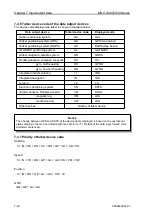
Chapter 7 Input/output data
MDC-7000/7900 Series
7-10
0092669002-07
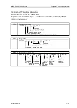
GBS
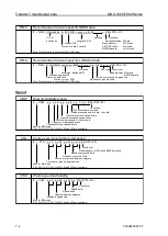
GNSS satellite fault detection
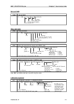
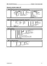
h *hh <CR><LF>
This field is not used.
Check sum
These fields are not used.
Expected error in longitude
Expected error in latitude
x.x, h,
x.x, x.x,
xx,
x.x, x.x,
$ -- GBS, hhmmss.ss, x.x,
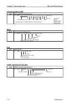
Loran-C position (LOP)
GLC
Geographic Position Loran-C
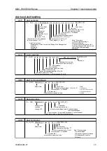
TD1
TD2
TD3
TD4
TD5
Check sum
Note*: Status
These fields are not used. status* status* status* status*
status*
A=Valid
B=Blink w arning
Note: When only tw o TD data are effective, TD data is displayed.
C=Cycle w arning
S=SNR w arning
a *hh<CR><LF>
x.x, a, x.x, a, x.x,
a, x.x, a, x.x, a,
$ -- GLC, xxxx, x.x,
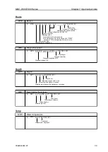
Wind
MWD
Wind direction and speed
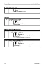
*hh<CR><LF>
Check sum
Wind speed, m/s
Wind speed, knots
Wind direction, 0° to 359° magnetic
Wind direction, 0° to 359° true
$ --
MWD,
x.x, T, x.x, M, x.x, N, x.x, M,
ROT
ROT
Rate of turn
*hh<CR><LF>
Check sum
Status, A=Valid V=Invalid
Rate of turn,
o
/min
"-" bow turns to port
$ -- ROT, x.x, A,
GNSS satellite fault detection
Summary of Contents for MDC-7006
Page 1: ......
Page 2: ......
Page 44: ...Chapter 3 installation method MDC 7000 7900 Series 3 24 0092669002 07 Unit mm inch MRM 108 ...
Page 96: ... This page intentionally left blank ...
Page 134: ... This page intentionally left blank ...
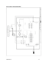
Page 155: ...0092669002 07 A 1 INTER CONNECTION DIAGRAM RB807 ...
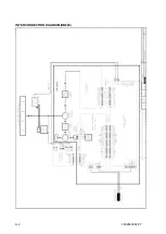
Page 156: ...A 2 0092669002 07 INTER CONNECTION DIAGRAM RB808 ...
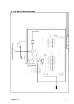
Page 157: ...0092669002 07 A 3 INTER CONNECTION DIAGRAM RB809 ...
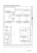
Page 158: ...A 4 0092669002 07 INTER CONNECTION DIAGRAM MRD 108 MRO 108 ...
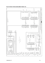
Page 159: ...0092669002 07 A 5 INTER CONNECTION DIAGRAM MRM 108 MRO 108 ...
Page 160: ......

