Chapter 4 Setup after installation
MDC-7000/7900 Series
4-10
0092669002-07
4.1.11 LOGO
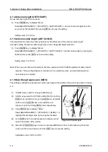
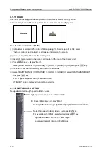
This radar can display your favorite picture or characters at wait or standby mode.
It is necessary to load data as
“logo.bmp” file beforehand to let you display this.
How to make and load the data file
(1) Edit a letter or picture in 256 colors of bitmap using PC. Size is up to 512x384 pixels.
The black color is not displayed as a transparent color on the screen.
(2) Save it as logo.bmp file to an SD memory card.
(3) Insert SD memory card in the upper card reader on the rear of the Display unit.
(4) Press MENU key to display
“Menu”.
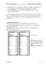
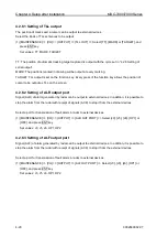
Select [MAINTENANCE] => [STARTUP] => [LOGO] => [LOAD] => [GO], and press ENT key.
(5) 5 sec. later, remove SD memory card from the card reader.
(6) Select [MAINTENANCE] => [STARTUP] => [LOGO] => [LOGO] => select [WAIT] or [STANDBY]
And press ENT key.
WAIT: Logo is displayed during countdown time.
STANDBY: Logo is displayed during standby mode.
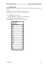
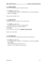
4.1.12 MOTOR HIGH SPEED
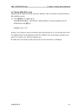
Set up when antenna high speed rotation is used.
KODEN
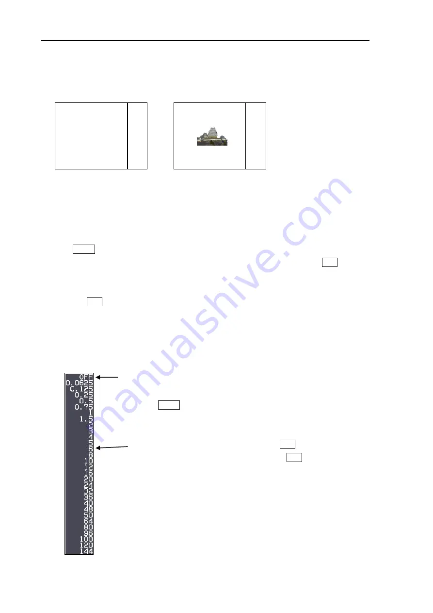
High speed rotation is not available in OFF.
(1) Press MENU key to display
“Menu”.
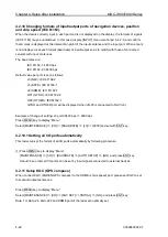
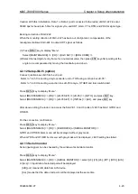
Select [MAINTENANCE] => [STARTUP] => [MOTOR HIGH SPEED].
Select high speed rotation range, then press ENT key.
For example, when 6NM is selected and press ENT key.
High speed rotation in 0.0625 to 6NM range
Low speed (normal) rotation in 8 NM or up.
Summary of Contents for MDC-7006
Page 1: ......
Page 2: ......
Page 44: ...Chapter 3 installation method MDC 7000 7900 Series 3 24 0092669002 07 Unit mm inch MRM 108 ...
Page 96: ... This page intentionally left blank ...
Page 134: ... This page intentionally left blank ...
Page 155: ...0092669002 07 A 1 INTER CONNECTION DIAGRAM RB807 ...
Page 156: ...A 2 0092669002 07 INTER CONNECTION DIAGRAM RB808 ...
Page 157: ...0092669002 07 A 3 INTER CONNECTION DIAGRAM RB809 ...
Page 158: ...A 4 0092669002 07 INTER CONNECTION DIAGRAM MRD 108 MRO 108 ...
Page 159: ...0092669002 07 A 5 INTER CONNECTION DIAGRAM MRM 108 MRO 108 ...
Page 160: ......

