MDC-7000/7900 Series
Chapter 7 Input/output data
0092669002-07
7-1
Chapter 7 Input/output data
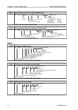
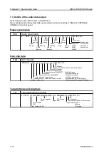
7.1 Details of the data input format
Check sum: All the data from $ to the check sum position * is calculated by exclusive-OR operation and
used as checksum.
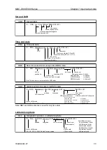
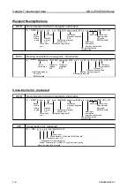
Heading
THS
True heading and status
a*hh<CR><LF>
Note* mode indicator
Check sum
A=Autonomous valid
Mode indicator*
E=Estimated invalid
Heading, degrees true
M=Manual input invalid
S=Simulator mode invalid
Note for IMO mode
V=Data not valid invalid
II, IN, HE, HN, HC, GA, GP, GL, GN and SN are accepted.
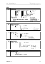
HDT
Heading true
T*hh<CR><LF>
Check sum
Heading, degrees true
Note for IMO mode
II, IN, HE, HN, HC, GA, GP, GL, GN and SN are accepted.
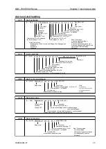
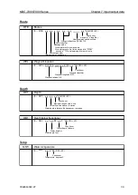
HDG
Heading, deviation and variation
*hh<CR><LF>
Check sum
Magnetic variation, degrees
Magnetic variation, degrees
Magnetic sensor heading, degrees
Note: This sentence is not accepted for IMO radar.
HDM
Heading Magnetic
M*hh<CR><LF>
Check sum
Heading, degrees magnetic
Note: This sentence is not accepted for IMO radar.
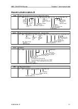
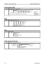
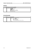
VTG
Course over ground and ground speed
a*hh<CR><LF>
Check sum
Mode indicator A/P/D=Valid, E/M/S/N=Invalid
Speed over ground, km/h
Speed over ground, knots
Course over ground, degrees magnetic
Course over ground, degrees true
K,
T, x.x, M, x.x, N, x.x,
$ -- HDM, x.x,
$ -- VTG, x.x,
$ -- HDG, x.x, x.x, E/W, x.x, E/W,
$ -- THS, x.x,
$ -- HDT, x.x,
Summary of Contents for MDC-7006
Page 1: ......
Page 2: ......
Page 44: ...Chapter 3 installation method MDC 7000 7900 Series 3 24 0092669002 07 Unit mm inch MRM 108 ...
Page 96: ... This page intentionally left blank ...
Page 134: ... This page intentionally left blank ...
Page 155: ...0092669002 07 A 1 INTER CONNECTION DIAGRAM RB807 ...
Page 156: ...A 2 0092669002 07 INTER CONNECTION DIAGRAM RB808 ...
Page 157: ...0092669002 07 A 3 INTER CONNECTION DIAGRAM RB809 ...
Page 158: ...A 4 0092669002 07 INTER CONNECTION DIAGRAM MRD 108 MRO 108 ...
Page 159: ...0092669002 07 A 5 INTER CONNECTION DIAGRAM MRM 108 MRO 108 ...
Page 160: ......

