MDC-7000/7900 Series
Chapter 4 Setup after installation
0092669002-07
4-17
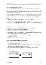
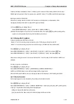
4.2.5.1 How to input the COG value by manual
(1) [MAINTENANCE] => [I/O] => [COG/SOG] => [COG MAN] => [VALUE] will show the current setting
of the input value by highlighting the last digit value by the trackball.
(2) Move the TRACKBALL up or down to set the value. Press ENT key to save the set result.
Setting value: 0.0 to 359.9°
Note:
The manual input data is displayed with yellow color.
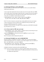
4.2.5.2 How to input the SOG value by manual
(1) [MAINTENANCE] => [I/O] => [COG/SOG] => [SOG MAN] => [VALUE] will show the current setting
of the input value by highlighting the last digit value by the trackball.
(2) Move the TRACKBALL up or down to set the value. Press ENT key to save the set result.
Setting value: 0.0 to 100.0 kn
Note:
The manual input data is displayed with yellow color.
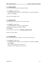
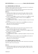
4.2.6 Setting of SET/DRIFT to be used for CURRENT mode
When [CURRENT] is selected in
“4.2.4” (STW) and “4.2.5” (COG/SOG), the device to input SET/DRIFT
is selected.
Select the sensor of SET/DRIFT when [CURRENT] is selected at STW and COG/SOG.
(1) [MAINTENANCE] => [I/O] => [SET/DRIFT] => [SET/DRIFT] => [VDR] or [MAN], and press ENT
key.
Set values: VDR, MAN
MAN: Use SET/DRIFT value manually input.
Note: AIS display does not work when [MAN] is selected.
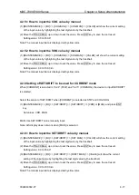
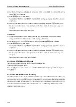
4.2.6.1 How to input the SET/DRIFT value by manual
(1) [MAINTENANCE] => [I/O] => [SET/DRIFT] => [SET MAN] => [VALUE] will show the current setting
of the input value by highlighting the last digit value by the trackball.
(2) Move the TRACKBALL up or down to set the value. Press ENT key to save the set result.
Setting value: 0.0 to 359.9°
(3) [MAINTENANCE] => [I/O] => [SET/DRIFT] => [DRIFT MAN] => [VALUE] will show the current
setting of the input value by highlighting the last digit value by the trackball.
(4) Move the TRACKBALL up or down to set the value. Press ENT key to save the set result.
Setting value: 0.0 to 100.0 kn
Note:
The manual input data is displayed with yellow color.
Summary of Contents for MDC-7006
Page 1: ......
Page 2: ......
Page 44: ...Chapter 3 installation method MDC 7000 7900 Series 3 24 0092669002 07 Unit mm inch MRM 108 ...
Page 96: ... This page intentionally left blank ...
Page 134: ... This page intentionally left blank ...
Page 155: ...0092669002 07 A 1 INTER CONNECTION DIAGRAM RB807 ...
Page 156: ...A 2 0092669002 07 INTER CONNECTION DIAGRAM RB808 ...
Page 157: ...0092669002 07 A 3 INTER CONNECTION DIAGRAM RB809 ...
Page 158: ...A 4 0092669002 07 INTER CONNECTION DIAGRAM MRD 108 MRO 108 ...
Page 159: ...0092669002 07 A 5 INTER CONNECTION DIAGRAM MRM 108 MRO 108 ...
Page 160: ......

