MDC-7000/7900 Series
Chapter 3 Installation method
0092669002-07
3-17
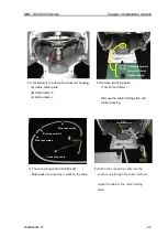
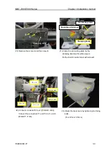
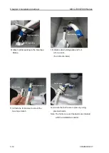
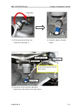
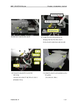
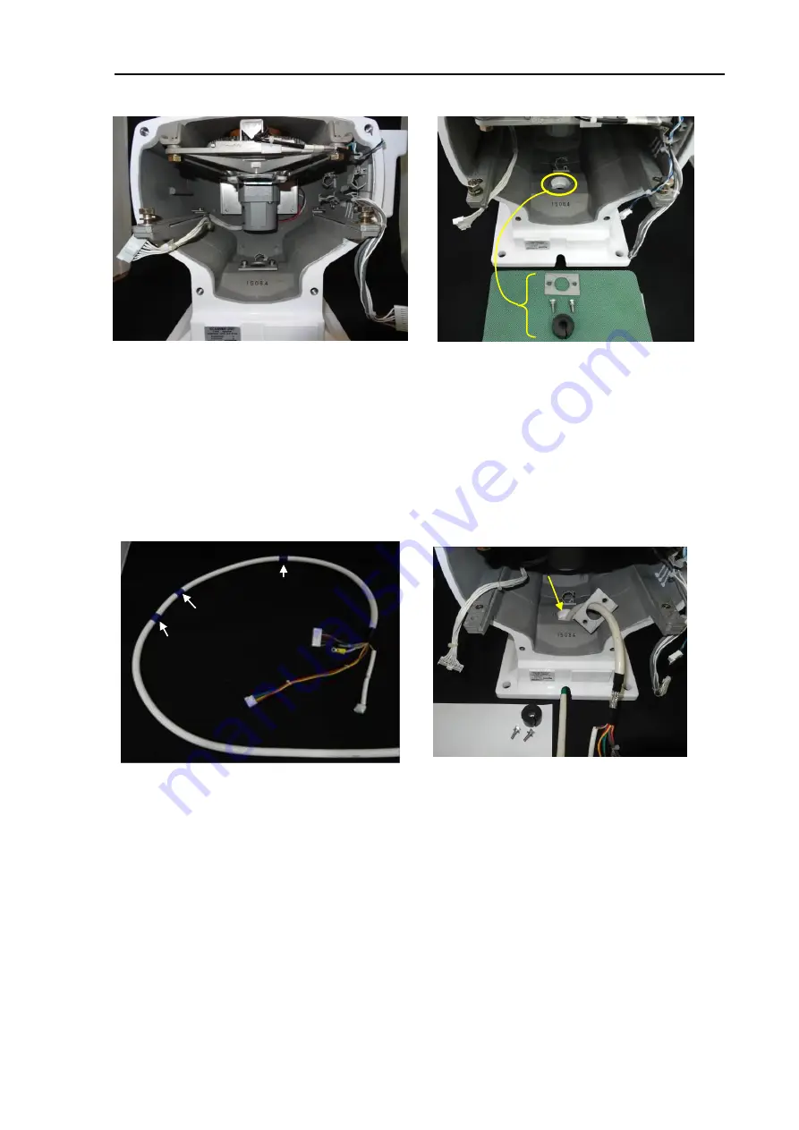
6) Remove the fixing two bolts.
(Tool: Wrench 8mm)
Remove cable holding plate and
rubber packing.
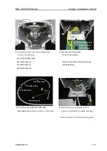
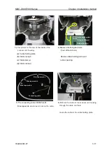
5)
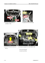
This picture is the view of the inside of the
scanner unit housing.
(
a
)
Cable holding plate
(
b
) Cable clamp-b
(
c
) Cable clamp-c
(
d
) Cable clamp-d
(
a
)
(
b
)
(
c
)
(
d
)
Cable holding plate
Fixing bolt (8mm)
Rubber packing
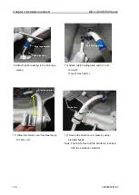
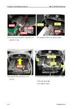
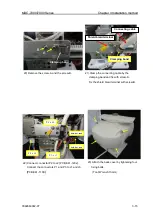
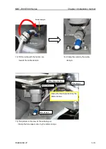
8) Pull
into the inside of the scanner unit housing
through the cable inlet hole.
Guide the cable to the cable holding plate.
Cable inlet hole
7) The connecting cable CW-845-xxM
Blue tapes are
wound as a mark on the cable.
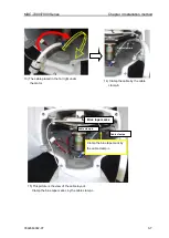
Blue tape mark-b
Blue tape mark-a
Blue tape mark-c
Connecting cable
Summary of Contents for MDC-7006
Page 1: ......
Page 2: ......
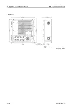
Page 44: ...Chapter 3 installation method MDC 7000 7900 Series 3 24 0092669002 07 Unit mm inch MRM 108 ...
Page 96: ... This page intentionally left blank ...
Page 134: ... This page intentionally left blank ...
Page 155: ...0092669002 07 A 1 INTER CONNECTION DIAGRAM RB807 ...
Page 156: ...A 2 0092669002 07 INTER CONNECTION DIAGRAM RB808 ...
Page 157: ...0092669002 07 A 3 INTER CONNECTION DIAGRAM RB809 ...
Page 158: ...A 4 0092669002 07 INTER CONNECTION DIAGRAM MRD 108 MRO 108 ...
Page 159: ...0092669002 07 A 5 INTER CONNECTION DIAGRAM MRM 108 MRO 108 ...
Page 160: ......

