Chapter 7 Input/output data
MDC-7000/7900 Series
7-2
0092669002-07
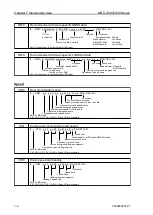
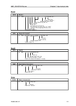
RMC
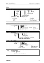
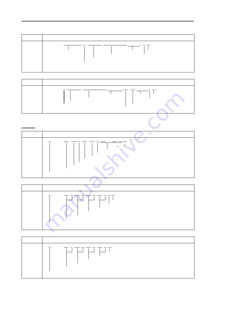
Recommended minimum specific GNSS data
a*hh<CR><LF>
UTC of
Not used
Check sum
position fix
Longitude, E/W
Navigation status S=Safe
Latitude, N/S
Mode indicator
C=Caution
Status, A=Valid V=Invalid
A/D/P/R/F=Valid
U=Unsafe
E/M/S/N=Invalid
V=Not valid
Note: This sentence is not accepted for IMO radar.
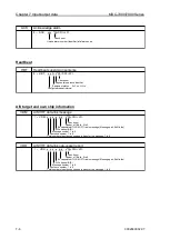
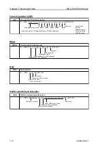
RMA
Recommended minimum specific LORAN-C data
a*hh<CR><LF>
Not used
Not used
Check sum
Longitude, degrees E/W
Mode indicator, A/D=valid
Latitude, degrees N/S
E/M/S/N=invalid
Status, A=data valid,
Course over ground, degrees true
V=blink, cycle or SNR
Speed over ground, knots
Note: This sentence is not accepted for IMO radar.
x.x, x.x, x.x,
a,
, , , , ,
a,
$ -- RMA, A, llll.ll, N/S, yyyyy.yy, E/W, x.x, x.x,
$ -- RMC, hhmmss.ss, A, llll.ll, N/S, yyyyy.yy, E/W,
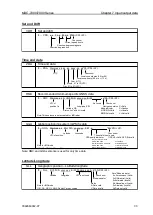
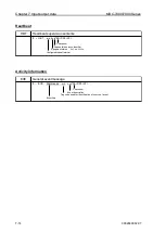
Speed
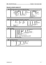
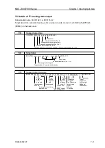
VBW
Dual ground/water speed
A*hh<CR><LF>
Check sum
These fields are not used
Status ground speed, A=Valid, V=Invalid
Transverse ground speed, knots
Longitudinal ground speed, knots
Status w ater speed, A=Valid, Invalid
Tranverse w aterspeed, knots
Longitudinal w ater speed, knots
Note for IMO mode
II, IN, VD, GA, GP, GL, GN, SN, VM and VW are accepted.
VTG
Course over ground and ground speed
a*hh<CR><LF>
Check sum
Mode indicator A/P/D=Valid, E/M/S/N=Invalid
Speed over ground, km/h
Speed over ground, knots
Course over ground, degrees magnetic
Course over ground, degrees true
Note for IMO mode
II, IN, VD, GA, GP, GL, GN, SN, VM and VW are accepted.
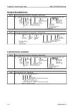
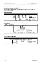
VHW
Water speed and heading
K*hh<CR><LF>
Check sum
Speed, km/h
Speed, knots
Heading, degrees magnetic
Heading, degrees true
Note for IMO mode
II, IN, VD, GA, GP, GL, GN, SN, VM and VW are accepted.
x.x, M, x.x, N, x.x,
$ -- VHW, x.x, T,
A, x.x,
$ -- VTG, x.x, T, x.x, M, x.x, N, x.x, K,
A, x.x, x.x, A, x.x,
$ -- VBW, x.x, x.x,
Summary of Contents for MDC-7006
Page 1: ......
Page 2: ......
Page 44: ...Chapter 3 installation method MDC 7000 7900 Series 3 24 0092669002 07 Unit mm inch MRM 108 ...
Page 96: ... This page intentionally left blank ...
Page 134: ... This page intentionally left blank ...
Page 155: ...0092669002 07 A 1 INTER CONNECTION DIAGRAM RB807 ...
Page 156: ...A 2 0092669002 07 INTER CONNECTION DIAGRAM RB808 ...
Page 157: ...0092669002 07 A 3 INTER CONNECTION DIAGRAM RB809 ...
Page 158: ...A 4 0092669002 07 INTER CONNECTION DIAGRAM MRD 108 MRO 108 ...
Page 159: ...0092669002 07 A 5 INTER CONNECTION DIAGRAM MRM 108 MRO 108 ...
Page 160: ......

