Chapter 3 installation method
MDC-7000/7900 Series
3-14
0092669002-07
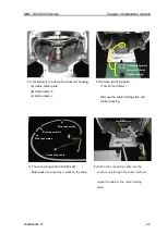
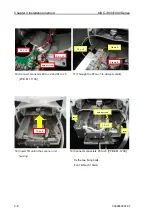
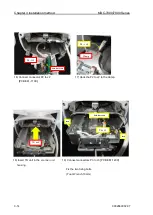
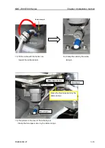
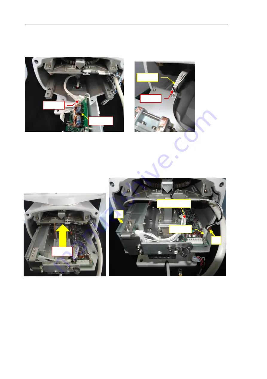
19) Connect connectors P3 to J3 [PCB E61-120X]
Fix the two fixing bolts.
(Tool: Wrench 13mm)
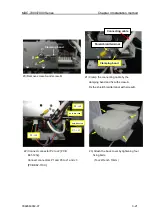
16) Connect connector P2 to J2
[PCB E61-110X].
P2 -> J2
PCB: E61-110X
17) Hook the P2 to J2 to the clamp.
P2 -> J2
Clamp
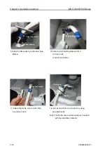
18) Insert TR unit in the
scanner unit
housing.
TR unit
PCB: E61-120X
P3-> J3
Bolt
Bolt
Summary of Contents for MDC-7006
Page 1: ......
Page 2: ......
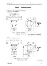
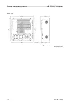
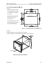
Page 44: ...Chapter 3 installation method MDC 7000 7900 Series 3 24 0092669002 07 Unit mm inch MRM 108 ...
Page 96: ... This page intentionally left blank ...
Page 134: ... This page intentionally left blank ...
Page 155: ...0092669002 07 A 1 INTER CONNECTION DIAGRAM RB807 ...
Page 156: ...A 2 0092669002 07 INTER CONNECTION DIAGRAM RB808 ...
Page 157: ...0092669002 07 A 3 INTER CONNECTION DIAGRAM RB809 ...
Page 158: ...A 4 0092669002 07 INTER CONNECTION DIAGRAM MRD 108 MRO 108 ...
Page 159: ...0092669002 07 A 5 INTER CONNECTION DIAGRAM MRM 108 MRO 108 ...
Page 160: ......


