Chapter 4 Setup after installation
MDC-7000/7900 Series
4-14
0092669002-07
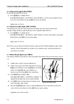
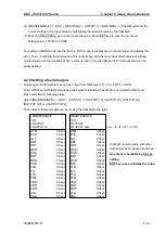
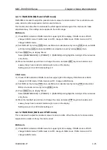
4.2.2 How to use without NMEA input connection
To use the function of this radar effectively, the default is set provided that all external input shall be
connected at the initial status. Therefore, when only basic function of radar (excluding navigation
function, mapping function, display of data, TT (ARPA) and AIS, etc.) will be used without connection to
other devices, an alarm with sound is displayed to remind an operator of input of ship
’s bearing, ship’s
speed and latitude and longitude. Please use this radar with keeping the ship
’s bearing, ship’s speed
and latitude and longitude OFF as follows.
Method of setting
Press MENU key to display
“Menu” and set as follows with the track ball.
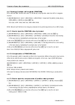
When HDG is not input (GPS compass and GYRO are not connected):
(1) [ALARM] => [ALARM ON/OFF] => [I/O] => [HDG INPUT] => [OFF], and press ENT key.
When SPD is not input (LOG and GPS are not connected):
(1) [ALARM] => [ALARM ON/OFF] => [I/O] => [SPD INPUT] => [OFF], and press ENT key.
When LAT/LON is not input (GPS and PLOTTER are not connected):
(1) [ALARM] => [ALARM ON/OFF] => [I/O] => [LAT/LON INPUT] => [OFF], and press ENT key.
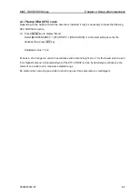
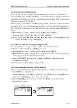
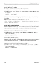
4.2.3 Set up Heading interfaces
4.2.3.1 Connection of KODEN GPS compass
Connect GPS compass to the SDME port. Refer to
“3.4.8 GPS compass connection”.
Press MENU key to display
“Menu” and set as follows with the track ball.
(1) [MAINTENANCE] => [I/O] => [HDG] => [HDG] => [AUTO], and press ENT key.
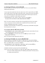
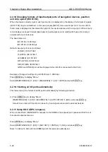
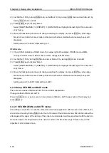
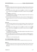
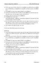
Initialize GPS compass (DATA 1 or DATA 2 in KGC-222, DATA 2 in KGC-1 and SDME port of the radar
are optimally reset.)
(1) [MAINTENANCE] => [I/O] => [KGC SET] => [INITIAL] => [GO], and press ENT key.
Note: With this initialization, port connected to the radar of GPS compass is set at 38400 bps, 50 ms for
signal cycle, and HDT, GGA, VTG, DTM and ZDA for signal type.
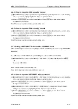
Compensate angles of GPS compass
When mounting direction of GPS compass has been out of alignment, compensation of the
misalignment allows GPS compass to output HDT signals as follows.
(1) [MAINTENANCE] => [I/O] => [KGC SET] => [BRG CORR] => [0.0°], and then select the last digit of
entry frame for a numerical value and set with ENT key after pointing at the angle to be
compensated by moving the trackball up and down.
Summary of Contents for MDC-7006
Page 1: ......
Page 2: ......
Page 44: ...Chapter 3 installation method MDC 7000 7900 Series 3 24 0092669002 07 Unit mm inch MRM 108 ...
Page 96: ... This page intentionally left blank ...
Page 134: ... This page intentionally left blank ...
Page 155: ...0092669002 07 A 1 INTER CONNECTION DIAGRAM RB807 ...
Page 156: ...A 2 0092669002 07 INTER CONNECTION DIAGRAM RB808 ...
Page 157: ...0092669002 07 A 3 INTER CONNECTION DIAGRAM RB809 ...
Page 158: ...A 4 0092669002 07 INTER CONNECTION DIAGRAM MRD 108 MRO 108 ...
Page 159: ...0092669002 07 A 5 INTER CONNECTION DIAGRAM MRM 108 MRO 108 ...
Page 160: ......

