MDC-7000/7900 Series
Chapter 5 Troubleshooting and on board repair
0092669002-07
5-19
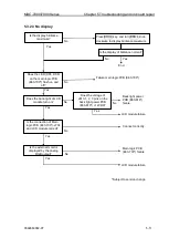
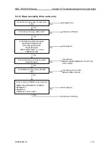
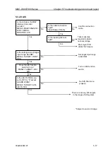
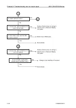
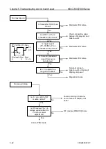
+250 V and frame is
shorted.
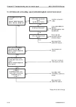
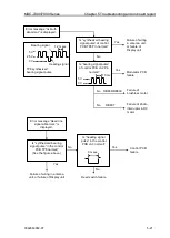
Pulse width control
failure
TP_PLUSE_W shape
A
B
5 V
0 V
Pulse length A (us) B (ms)
L2
1.4
1.5 to 1.6
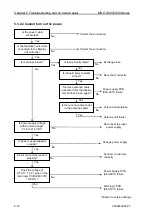
Does status recover by
disconnecting P2 (J2)
connector from modulator
PCB?
No
Antenna unit wiring failure
or Display unit failure
Yes
Modulator PCB failure
No
Yes
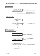
Is transmitter unit drive signal
(modulator PCB TP_PLUSE_W)
normal?
Modulator PCB failure
Yes
Modulator PCB
failure
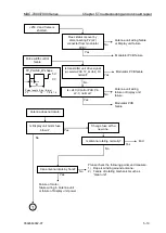
Is +24V (Control PCB Pin
J2-1) normal?
Antenna unit wiring
failure or Display unit
failure
No
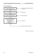
Please check the following points and measure.
1) Rope is winding around antenna.
2) Failure of rotating mechanism such as
“Gear unit”
Failure of motor,
failure wiring in Antenna unit
or failure of Display unit power
No
Yes
No
Change fuse with a
new one.
End
Is antenna rotating normally?
Yes
No
Can antenna rotate by hand?
Is Display unit motor fuse
blown?
Yes
Antenna does not rotate.
1
Summary of Contents for MDC-7006
Page 1: ......
Page 2: ......
Page 44: ...Chapter 3 installation method MDC 7000 7900 Series 3 24 0092669002 07 Unit mm inch MRM 108 ...
Page 96: ... This page intentionally left blank ...
Page 134: ... This page intentionally left blank ...
Page 155: ...0092669002 07 A 1 INTER CONNECTION DIAGRAM RB807 ...
Page 156: ...A 2 0092669002 07 INTER CONNECTION DIAGRAM RB808 ...
Page 157: ...0092669002 07 A 3 INTER CONNECTION DIAGRAM RB809 ...
Page 158: ...A 4 0092669002 07 INTER CONNECTION DIAGRAM MRD 108 MRO 108 ...
Page 159: ...0092669002 07 A 5 INTER CONNECTION DIAGRAM MRM 108 MRO 108 ...
Page 160: ......


