MDC-7000/7900 Series
Chapter 4 Setup after installation
0092669002-07
4-31
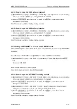
4.4.4 Setup GAIN OFFSET mode
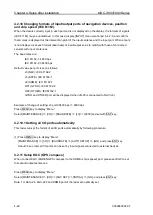
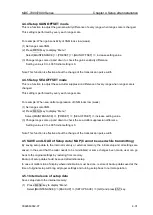
This is a function to adjust the gain sensitivity difference of every range when range scale is changed.
This setting is performed by every each range scale.
For example: When gain sensitivity of 3NM looks low (weak).
(1) Set range scale 3NM.
(2) Press MENU
key to display “Menu”.
Select [MAINTENANCE] => [PRESET] => [GAIN OFFSET] => increase setting value.
(3) Change range scale up and down to check the gain sensitivity difference.
Setting value is 0 to 4095: Initial setting is 0.
Note: This function is effective about the change of the transmission pulse width.
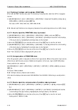
4.4.5 Setup SEA OFFSET mode
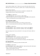
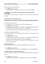
This is a function to adjust the sea clutter suppression difference of every range when range scale is
changed.
This setting is performed by every each range scale.
For example: When sea clutter suppression of 3NM looks low (weak).
(1) Set range scale 3NM.
(2) Press MENU
key to display “Menu”.
Select [MAINTENANCE] => [PRESET] => [SEA OFFSET] => increase setting value.
(3) Change range scale up and down to check the sea clutter suppression difference.
Setting value is 0 to 4095: Initial setting is 0.
Note: This function is effective about the change of the transmission pulse width.
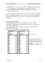
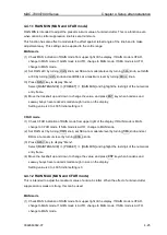
4.5 SAVE and LOAD of Setup data / MAP (Cannot be used while transmitting)
By saving setup data to the internal memory or external memory, the initial setup and all settings are
saved, in the event that the radar needs to be reinitialized or some changes been made, user can go
back to the original settings by restoring from memory.
Backup of setup data should be saved after initial setup.
In case of malfunction of display where initialization must be done, restore of backup data saved at the
time of original setup will bring all proper settings and turning setup back to normal operation.
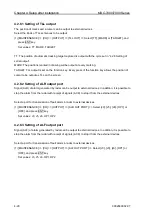
4.5.1 Internal save of setup data
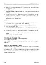
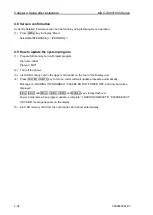
Save setup data to the internal memory:
(1) Press MENU key to display
“Menu”.
Select [MAINTENANCE] => [BACKUP] => [SETUP SAVE] => [GO] and press ENT key.
Summary of Contents for MDC-7006
Page 1: ......
Page 2: ......
Page 44: ...Chapter 3 installation method MDC 7000 7900 Series 3 24 0092669002 07 Unit mm inch MRM 108 ...
Page 96: ... This page intentionally left blank ...
Page 134: ... This page intentionally left blank ...
Page 155: ...0092669002 07 A 1 INTER CONNECTION DIAGRAM RB807 ...
Page 156: ...A 2 0092669002 07 INTER CONNECTION DIAGRAM RB808 ...
Page 157: ...0092669002 07 A 3 INTER CONNECTION DIAGRAM RB809 ...
Page 158: ...A 4 0092669002 07 INTER CONNECTION DIAGRAM MRD 108 MRO 108 ...
Page 159: ...0092669002 07 A 5 INTER CONNECTION DIAGRAM MRM 108 MRO 108 ...
Page 160: ......

