MDC-5200/5500 Series
Chapter 6 Maintenance
0092655002-03
6-13
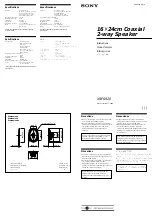
3) Unsolder the yellow wire and green wire from the pulse transformer
terminals.
Remove the four screws that secure the magnetron.
Remove the magnetron from the chassis.
Remove four screws.
Unsolder two wires.
Yellow wire
Terminal-6
Green wire
Terminal-8
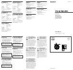
4) This picture is the view of the modulator with magnetron removed.
Chassis
Four screw holes for mounting the magnetron.
Terminal-6
Terminal-8
Terminal-6
Summary of Contents for MDC-5204
Page 1: ......
Page 2: ......
Page 26: ...Chapter 3 Installation method MDC 5200 5500 Series 3 2 0092655002 03 RB808 RB809 Unit mm inch ...
Page 70: ... This page intentionally left blank ...
Page 154: ... This page intentionally left blank ...
Page 174: ... This page intentionally left blank ...
Page 175: ...0092655002 03 A 1 INTER CONNECTION DIAGRAM RB806 ...
Page 176: ...A 2 0092655002 03 INTER CONNECTION DIAGRAM RB807 ...
Page 177: ...0092655002 03 A 3 INTER CONNECTION DIAGRAM RB808 ...
Page 178: ...A 4 0092655002 03 INTER CONNECTION DIAGRAM RB809 ...
Page 179: ...0092655002 03 A 5 INTER CONNECTION DIAGRAM MRD 109 MRO 108 ...
Page 180: ...A 6 0092655002 03 INTER CONNECTION DIAGRAM MRD 111 ...
Page 181: ......
Page 182: ......