8. Peripherals and Options
- 255 -
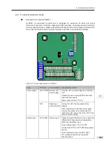
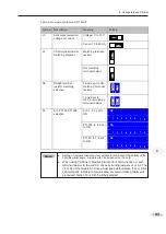
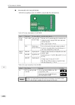
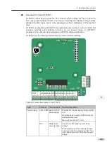
Setting of jumpers takes top view with main terminals at the bottom of the
card as visual angle. Jumpers are silk-screened on the card.
8
Jumper
J3
Description
AO2 output
selection: voltage
or current
Meaning
Voltage
Setting
Current
J1
RS485 terminal
resistor matching
selection
J7
Run/Stop
selection
Matching the terminal
resistor
Not matching the
terminal resistor
Run
Stop
J8
OP1 connecting
mode selection
If DI connected in
SINK mode, OP1
connected to +24V
If DI connected in
SOURCE mode, OP1
connected to COM
S1
AI3, PT100,
AI3: 1, 2, 3 set to ON
PT1000 selection
ON
PT1000: 4, 5, 6 set to
ON
ON
PT100: 6, 7, 8 set to
ON
ON
Note
Summary of Contents for GT600-4T132G
Page 1: ...GT600 AC Drive...
Page 5: ......
Page 86: ...5 Quick Setup 5 1 Get Familiar With Operating Panel 86 5 2 Setup Flowchart 87...
Page 87: ......
Page 100: ...5 Quick Setup 98 5...
Page 280: ...8 Peripherals and Options 278 8...
Page 306: ...12 303 11...
Page 362: ......


