7. Interfaces and Communication
- 221 -
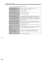
Terminal
Input Signal Characteristic
AI1-GND
It receives the signal of 0 to 10 VDC.
AI2-GND
If J9 jumps to the "V" position, AI receives voltage signal of 0 to 10 VDC.
If J9 jumps to the "I" position, AI receives current signal of 0 to 20 mA.
AI3-GND
It receives signal of -10 to 10 VDC.
7
Terminal
Corresponding Function Code
Output Feature Description
FM-CME
F5-06 when F5-00 = 0
Transistor
Able to output high-speed pulses 10 Hz to 100 KHz
Drive capacity: 24 VDC, 50 mA
F5-01 when F5-00 = 1
Transistor
Drive capacity: 24 VDC, 50 mA
TA-TB-TC
F5-02
Relay
Drive capacity: 50 VAC, 0.2 A/30 VDC, 1 A
PA-PB-PC
F5-03
Extension card, relay; drive capacity: 50 VAC, 0.2
A/30 VDC, 1 A
DO1-CME
F5-04
Transistor
Drive capacity: 24 VDC, 50 mA
DO2-CME
F5-05
Extension card transistor
Drive capacity: 24 VDC, 50 mA
When F5-00 = 0, FM terminal is high-speed pulse output. Frequency of pulses on this DO
terminal indicates the value of internal running parameters. Higher values of internal running
parameters produce higher pulse frequencies. Value 100% corresponds to a pulse frequency of
100 kHz.
■
Use of AI Terminals
The drive supports a maximum of three analog input terminals. Of these, AI1 and AI2 are on the
control board, and AI3 is on the optional extension card.
Analog inputs allow an external voltage or current signal to set frequency reference, torque
reference, voltage setting at V/F separation, and PID reference and feedback. F4-13 to F4-27
define relationship between analog input voltage or current signals and actual controlled setting
or feedback.
Sampling of analog values on AI terminals is possible by reading function codes:
●
U0-09 shows value of AI1.
●
U0-10 shows value of AI2.
●
U0-11 shows value of AI3.
■
Use of AO Terminals
The drive supports a maximum of two analog output terminals. AO1 is on the control board and
AO2 is on the optional extension card.
Summary of Contents for GT600-4T132G
Page 1: ...GT600 AC Drive...
Page 5: ......
Page 86: ...5 Quick Setup 5 1 Get Familiar With Operating Panel 86 5 2 Setup Flowchart 87...
Page 87: ......
Page 100: ...5 Quick Setup 98 5...
Page 280: ...8 Peripherals and Options 278 8...
Page 306: ...12 303 11...
Page 362: ......


