EonStor S12E-R1132-4/G1133-2 Installation and Hardware Reference Manual
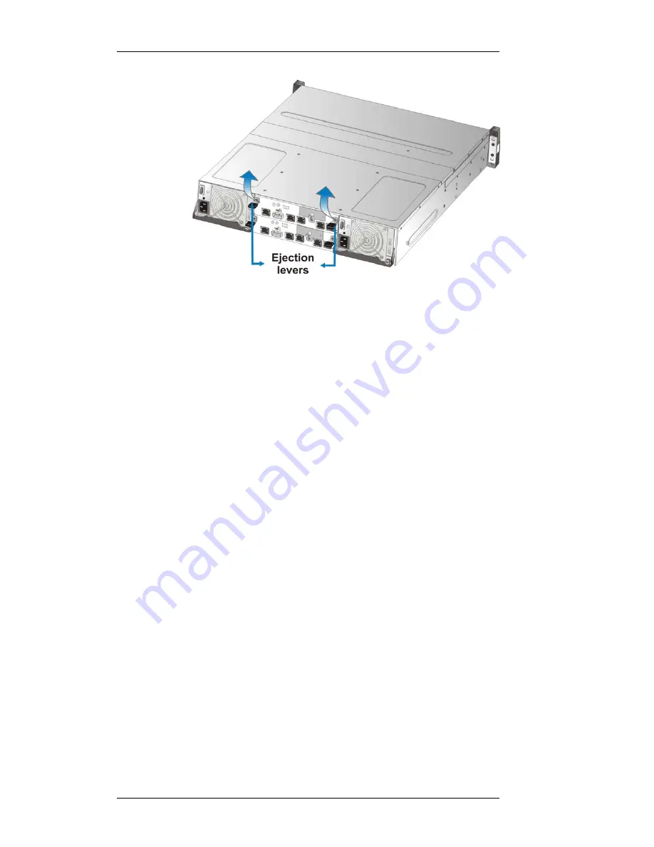
Figure 5-4: Using the Ejection Levers to Secure Controller
Step 7.
Secure the controller module to the chassis.
Fasten
the two (2) screws that secure the ejection levers.
Step 8.
Re-attach all cables
that were removed. These include
the cables that connect to the local network or iSCSI
initiators that were previously attached to the iSCSI
ports, and any cable that was attached to the RS-232C
audio jack connector.
5.2.3.2
Replacing a Controller Module on S12E-G1133-
2
To replace the controller module:
Step 1.
Prepare a clean, static-free work pad or container
to
place the removed controller.
Step
2.
Disconnect all cables from the failed controller
module
. These include the cables that connect to the
local network or iSCSI initiators that were previously
attached to the iSCSI ports, and any cable that was
attached to the RS-232C audio jack connector.
Step 3.
Loosen the captive screws
that secure the controller
to the chassis. (See
Figure 5-5
)
5-6


