EonStor S12E-R1132-4/G1133-2 Installation and Hardware Reference Manual
Step 2.
ightly more
force for the back-end connector to mate with
Step 3.
Secure the BBU to the subsystem
by fastening the
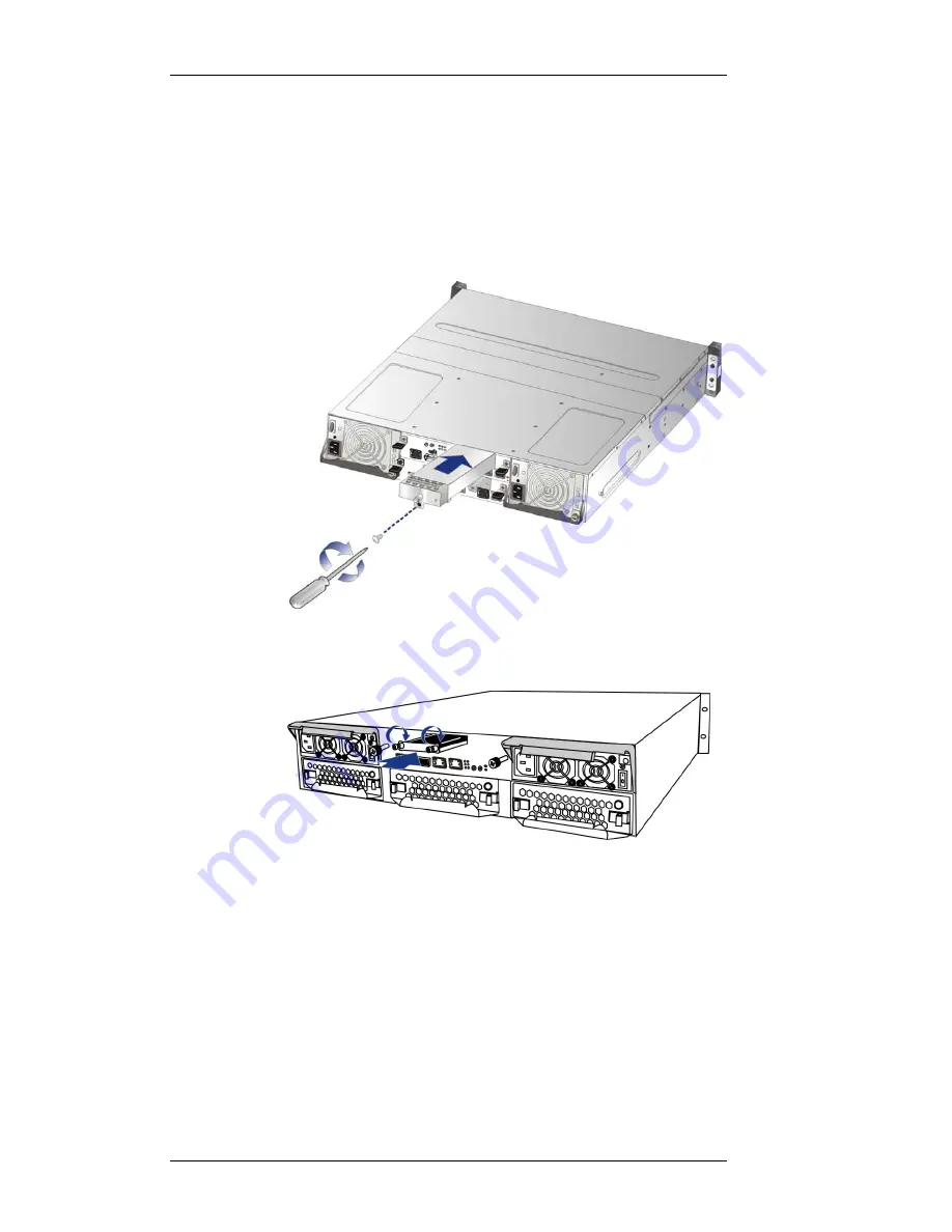
Install the replacement BBU.
Align the BBU with the
module bay, and then gently push the BBU into the bay.
When you feel the contact resistance, use sl
corresponding connector on the backplane.
retention screw(s). (See
Figure 5-12
and
Figure 5-13
)
Figure 5-12: Installing the BBU on S12E-R1132-4
Figure 5-13: Installing the BBU on S12E-G1133-2
Step 4.
BU is being charged. When the BBU
is fully charged, the LED will go off. (See
Figure 5-14
and
Figure 5-15
)
Reset the subsystem if the BBU is replaced online
.
After the system reset, the LED should start flashing to
indicate that the B
5-16


