NSM-8×1AES/NSM-7×2AES Installation and Operation Manual
41
Chapter 3: Operation
Preliminary—Contents are proprietary and confidential. Do not photocopy or distribute.
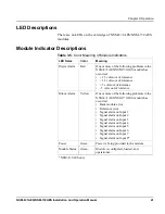
LED Descriptions
There are no LEDs on the card edge of NSM-8×1AES/NSM-7×2AES
modules.
Module Indicator Descriptions
Table 3-5.
Color Meaning of Module Indicators
LED Name
Color
Meaning
Major Alarm
Red
One or more of the following problems in the
NSM-8×1AES/NSM-7×2AES module has
occurred:
• + 2.5 volts out of tolerance
• + 3.3 volts out of tolerance
• + 5 volts out of tolerance
• - 5 volts out of tolerance
Minor Alarm
Yellow
One or more of the following problems in the
NSM-8×1AES/NSM-7×2AES module has
occurred:
• Back module error
• Reference error
• Signal alarm on Input 1
• Signal alarm on Input 2
• Signal alarm on Input 3
• Signal alarm on Input 4
• Signal alarm on Input 5
• Signal alarm on Input 6
• Signal alarm on Input 7
• Signal alarm on Input 8*
Power
Green
Power is being provided to the module.
Module Status
Green
Module is configured, loaded, and
operational.
*NSM-8×1AES only

