NSM-8×1AES/NSM-7×2AES Installation and Operation Manual
39
Chapter 3: Operation
Preliminary—Contents are proprietary and confidential. Do not photocopy or distribute.
State Recovery Parameter Availability
Every five minutes, the parameter settings for this module are
automatically saved onto the resource module installed in your NEO
frame. If a module should fail and be replaced with a cold spare, the
state parameters can be automatically recovered. For more information
on this feature, see the
NEO FR-3901, FR-3903, and FR-3923
Mounting Frames Installation and Operation Manual
(Edition E and
above).
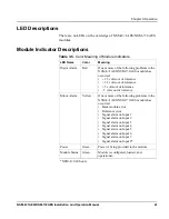
LEDs and Module Indicators
General Information
The NSM-8×1AES/NSM-7×2AES has four standard module
indicators:
•
Major alarm
•
Minor alarm
•
Power
•
Module status
These indicators are located on the card edge of the front module,
directly in front of the VFD. (See
Figure 3-3
.)
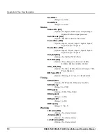
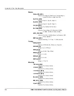
The NSM-8×1AES/NSM-7×2AES also generates alarm signals to alert
users of failures or impending failures within the module. These alarm
signals are found in the following locations:
•
As red or yellow LEDs on the 3901AIC Alarm Interconnect
Module or the 3901RES-E Resource Module (visible via light
pipes through the frame’s front panel)
•
As part of a list of activated alarms found in the
Setup
menu
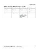
Input8*
Input 8 Alarm
Minor
Signal alarm on
Input 8
Ref_Error
Reference Error
Minor
Reference error
*NSM-8×1AES only
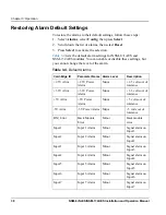
Table 3-4.
Default Alarms
(Continued)
Card-Edge ID
Parameter Name Alarm Level
Description


