34
NSM-8×1AES/NSM-7×2AES Installation and Operation Manual
Preliminary—Contents are proprietary and confidential. Do not photocopy or distribute.
Chapter 3: Operation
In 3 Sync
Input 3 Synchronous
Input 3 synchronous
• Yes*
• No
In 4 Sync
Input 4 Synchronous
Input 4 synchronous
• Yes*
• No
In 5 Sync
Input 5 Synchronous
Input 5 synchronous
• Yes*
• No
In 6 Sync
Input 6 Synchronous
Input 6 synchronous
• Yes*
• No
In 7 Sync
Input 7 Synchronous
Input 7 synchronous
• Yes*
• No
+5V Alrm
[RO]
+5V Power Alarm
+ 5 volts out of tolerance
• No Alarm
• Alarm
-5V Alrm
[RO]
-5V Power Alarm
– 5 volts out of tolerance
• No Alarm
• Alarm
+3.3V Alrm
[RO]
+3.3V Power Alarm
+ 3.3 volts out of
tolerance
• No Alarm
• Alarm
+2.5V Alrm
[RO]
+2.5V Power Alarm
+ 2.5 volts out of
tolerance
• No Alarm
• Alarm
Ref_Error
[RO]
Reference Error
Reference error
• No Alarm
• Alarm
BM_Error
[RO]
Back Module Error
Back module error
• No Alarm
• Alarm
Input1
[RO]
Input 1 Alarm
Signal alarm on Input 1
• No Alarm
• Alarm
Input2
[RO]
Input 2 Alarm
Signal alarm on Input 2
• No Alarm
• Alarm
Input3
[RO]
Input 3 Alarm
Signal alarm on Input 3
• No Alarm
• Alarm
Input4
[RO]
Input 4 Alarm
Signal alarm on Input 4
• No Alarm
• Alarm
Input5
[RO]
Input 5 Alarm
Signal alarm on Input 5
• No Alarm
• Alarm
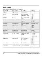
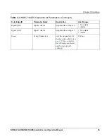
Table 3-3.
NSM-7×2AES Operator List Parameters
(Continued)
Card-Edge ID
Parameter Name
Description
User Range


