


13. JTAG > Dedicated Test Pins
113
PEB383 User Manual
July 25, 2011
Integrated Device Technology, Inc.
Confidential - NDA Required
•
Verify that the Ready bit is at logic high and the Error bit is at logic low.
Note
: To prevent corruption, the DR register must be loaded as described in step 2 while
shifting out through JTAG_TDO for observation.
5.
Go back to step 2 to perform another read.
13.7
Dedicated Test Pins
The following pins are dedicated to test:
•
TEST_ON (Scan shift enable; this signal is tied low for normal operation)
•
TEST_BCE (Boundary scan compliance enable; this signal is tied low for normal operation) – This
pin configures the SerDes built-in TAP controller and the PEB383 top-level TAP controller into a
daisy chain. TEST_BCE uses a pad with a built-in pull-up. When TEST_ BCE is low, the bridge’s
JTAG pins access only the top-level TAP controller. When TEST_BCE is high, the daisy chain
mode is selected (see
).
13.8
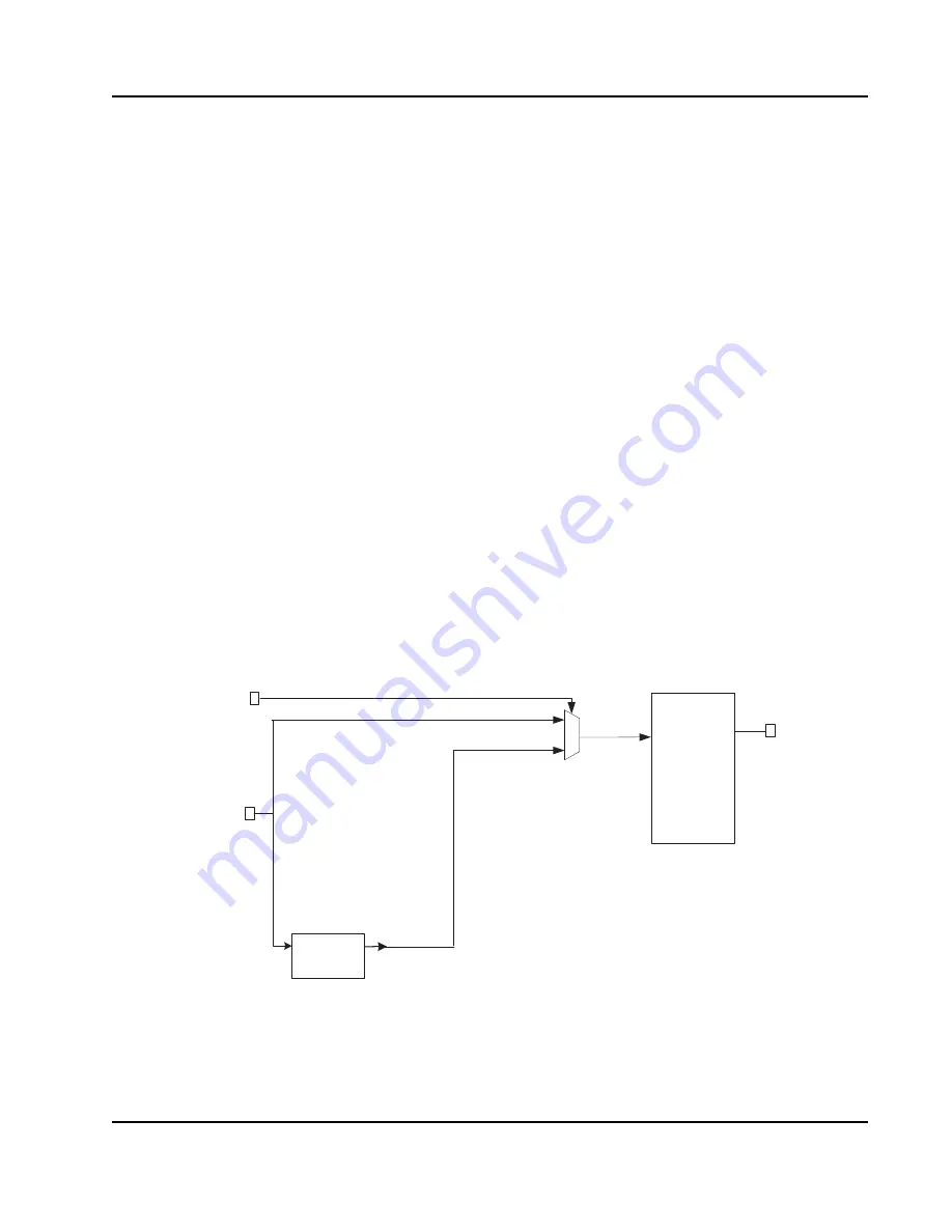
Accessing SerDes TAP Controller
The SerDes has an internal TAP controller that uses IDCODE instruction for the IP identification and
CRSEL instruction for writing and reading registers in the IP. To access the SerDes TAP controller
through JTAG pins, JTAG_TDI pin of SerDes is connected to the JTAG_TDI pin and the TDO of
SerDes is connected to the JTAG_TDI of the PEB383’s top-level TAP controller through a mux with
JTAG_BCE pin as selector.
shows the connections between the bridge’s TAP controller and
the SerDes TAP controller.
Figure 39: PCIe SerDes Connections
Serdes
TAP controller
tdi
tdo
TDO
TDI
0
1
Z
BCE
LV Tap
controller
tdi
tdo


