2-63
CAPACITY CONTROL MECHANISM
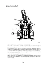
Figure typically shows the capacity control mechanism.
When high speed pilot line is charged with the pressure P
A
that overcome the spring (50), the
spring (50) is compressed and spool (46) shifts to the right to connect the port P and port C.
Then, the highest pressure is selected by the check valve (54) from inlet and outlet pressure of the
motor and high speed pilot line pressure and pushes shifter piston (6). As a result, swash plate (15)
turns around the line L which connect the two pivots (14) as shown by dotted lines. The turn stops
at the stopper (1-1) of casing and swash plate (15) keeps the position.
In this case, the piston stroke become shorter and motor capacity become smaller and motor
rotates faster, around 1.60 times, by the same volume of oil.
When no pressure is in the high speed pilot line P
A
, spool (46) is pushed back by the spring (50)
and pressure that pressed the shifter piston (6) is released to the hydraulic tank through restrictor
(57).
Here, nine pistons are there and they equally spaced on the swash plate (15). The force that
summed up those of pistons comes to almost the center of the swash plate (15) as shown. Since
the pivots (14) are off-set by S from the center, the rotating force of product S and the force moves
swash plate (15) to the former position and the speed returns to low.
When the power demand exceeds the engine power, such as in steep slope climbing or turning at
high speed mode, the system step down to the low speed automatically. The mechanism is that:
pump pressure is led to the port P
B
and this pressure activate on pin (49). When the pressure at P
B
exceeds predetermined value, spool (46) returns to the left by the counter-pressure against pin (49)
and the pressure on the shifter piston (6) through port C is released to the tank and the motor
comes to low speed.
When P
B
goes down, the spool (46) moves to the right and the speed become high.
3)
High speed pilot line
(External Pilot)
To counterbalance valve
(Brake valve)
MB
MA
54
54
54
13
6
1-1
20
14
14
Load
application point
L
L
S
46
P
C
VA or VB
57
50
49
T
P
A
P
B
15
43092TM06


