3-11
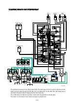
6. SWING PARKING BRAKE RELEASE
PS
(P4)
(P3)
N2
Pca
Dr3
P2c2
Ba
Aa
PAa
PBa
Bo
Ao
PAo
PBo
(Ck2)
Drb
PBb2
PSp
Dra
Bs
As
PAs
PBs
Dr4
Pns
Br
Ar
PAr
PBr
R3
TRAVEL(RH)
SWING
BOOM 2
T1
Pa
P2
P1 P1g
P2g
R4
(PTb)
PS
PL1
Py
PBL
PAL
PBb
PAb
Ab
Bb
P2c1
Dr3'
PBc
PAc
PAcs
Bc
Ac
PBa2
PAa2
Pcb
N1
OPTION
ARM 1
ARM 2
BUCKET
BOOM 1
TRAVEL(LH)
PS
PS
PS
PS
PS
A
B
C
TRAVEL
P
T
RCV PEDAL
(2)
PBr
(1)
PAr
(4)
PBL
(3)
PAL
BOOM
P
T
BUCKET
ARM
P
T
SWING
c
e2
d1
h1
h2
P2c1
PAb
(4)
PBc
Pca
PAc
PAcs
PBb2
PBb
PAa2
P2c2
PAa
PBa2
PBa
PBs
PAs
PSp
Dr#,dr#
T
LINE FILTER
P3
P2
P1
P4
Pns
(MCV)
PL1
(MCV)
P
(T/Joint)
A1
A2
A4
A5
SH
(2)
(1)
(3)
(4)
(2)
(3)
(1)
HYDRAULIC TANK
SH
PG
ARG
Dr
GA
A(CCW)
Mu
B(CW)
GB
Au
SGo
(RG)
Dr
SRG
BRAKE VALVE
TRAVEL MOTOR
SWING MOTOR
ARM
CYLINDER
BUCKET
CYLINDER
BOOM
CYLINDER
PILOT
PUMP
Px
P
BL
AL
PG(S/Motor)
Pa(MCV)
Psv1(M/PUMP)
P(MCV)
B
a
b
d
e
f
g
h
j
PUMP
A1
PUMP
A2
A
D
E
F
G
H
J
380L3HC07
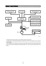
When one of the RCV lever (except travel lever) is tilted, the pilot oil flows into SH port through main
control valve.
This pressure moves spool of the time delay valve so, discharged oil from pilot valve flows to swing
motor PG port. This pressure is applied to swing motor disc, thus the brake is released.
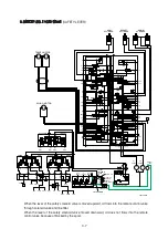
When all of the RCV lever are set in the neutral position, oil in the swing motor disc cylinder is
drained, thus the brake is applied.

