


4-9
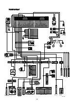
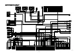
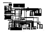
2. STARTING CIRCUIT
OPERATING FLOW
B) terminal Battery relay [CR-1] Circuit breaker [CN-60] Master switch [CS-74A]
Fuse box [No.5] Master switch [CS-74B] I/conn [CN-5 (36)] Start switch [CS-2A (1)]
Power relay [CR-35 (30)]
When start key switch is in ON position
Start switch ON [CS-2A (2)] I/conn [CN-5 (39)]
Battery relay [CR-1] Battery relay operating (all power is supplied with the electric component)
l/conn [CN-4 (4)] Emergency engine stop sw [CS-33 (2)
供
(1)] l/conn [CN-4 (13)]
Fuse box [No. 9] Engine ECM [CN-93 (5)]
Start switch ON [CS-2A (3)] GPS conn [CN-125 (2)
供
(4)]
I/conn [CN-5 (40)] Power relay [CR-35 (86)
供
(87)]
Fuse box [No.10] MCU [CN-51 (2)]
Reader [CN-427 (1)]
RMS [CN-125A (2)]
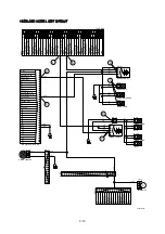
When start key switch is in START position
Start switch START [CS-2A (6)] I/conn [CN-5 (35)] Anti-restart relay [CR-5 (2)
供
(5)]
l/conn [CN-2 (7)] Start relay [CR-23 (2)] Starter motor is activated.
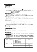
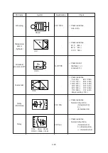
CHECK POINT
1)
(1)
(2)
2)
Engine
Start switch
Check point
Voltage
OPERATING
START
Η
- GND (battery)
Θ
- GND (start key)
Ι
- GND (battery relay M4)
Κ
- GND (starter B+)
Λ
- GND (starter M)
Μ
- GND (start relay)
Ν
- GND (battery relay M8)
20~25V