background image

Chapter 7.   PARAMETER SETUP

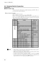
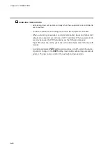
Modifying individual items and exiting the setting mode

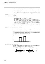
Pressing the 

ENTER key

while an individual item is displayed causes the set value to

flash and enables the registration state. At this point, the 

↑↑

key

and 

↓↓

key

allow you to

increase or decrease the values, while the 

key

and 

key

move the digit positions

on the display at which the values flash.

Pressing the 

ENTER key

after the flashing number has been changed to the desired

value stops the flashing, the number reverts to the on state and the new setting is stored

in internal memory.

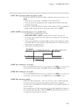
Modification of settings is terminated by pressing either the 

PARA key

(valid for vari-

able parameters and event configuration data), 

PID key

(valid for PID parameters and

constant value control data), 

SETUP key

(valid for setup data) or 

DISP key

. Pressing

the 

PARA key

PID key

or 

SETUP key

moves the cursor to the next item stops the

flashing and the number reverts to its normal on state.

Pressing the 

DISP key

enables the normal display mode.

Should display panel 2 showcduring display of an individual item or pressing the

ENTER key

not enable the registration state, it means that settings cannot be made or

modified for that item.

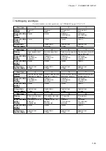
HANDLING PRECAUTIONS

• When 

PA01

is set to more than 1 in a variable parameter setting, 

PA03

and

items beyond are not displayed. 

PA03

and items beyond cannot be changed

when 

PA02

is set to more than 1.

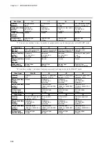
• Event configuration data settings cannot be changed when 

PA02

is set to a

value more than 1. Also, when 

PA02

is set to 0 or 1, the event type setting

and some auxiliary settings (output points of code events) cannot be
changed.

• PID parameter settings cannot be changed when 

PA02

is set to 4 or 5.

• Setup data settings cannot be changed when 

PA02

is set to a value more

than 1 and cannot be displayed in modes other than the READY mode.

• The constant value control data setting cannot be changed when 

PA02

is set

to 4 or 5. And, since the 

FUNC

and 

PID keys

are invalid in modes other than

the READY mode, a 

ConSt

setting cannot be displayed or changed.

7-2

Summary of Contents for DCP550

Page 1: ...EN1I 6186 Issue 13 04 08 DCP551 Mark ΙΙ Digital Control Programmer User s Manual www honeyvell energy ...

Page 2: ...f you encounter a problem with your unit please review all the configuration data to verify that your selections are consistent with your application i e Inputs Outputs Alarms Limits etc If the problem persists after checking the above parameters you can get technical assistance by calling the following In the U S A 1 800 423 9883 In Europe Your local branch office ...

Page 3: ...event injury to the operator and others and to prevent damage to proper ty Be sure to observe these safety precautions Examples Use caution when handling the product The indicated action is prohibited Be sure to follow the indicated instructions SAFETY PRECAUTIONS WARNING Warnings are indicated when mishandling this product might result in death or serious injury CAUTION Cautions are indicated whe...

Page 4: ...s caution may lead to fire or malfunction Be sure to follow the operating requirements regarding temperature humidity voltage vibration shock mounting direction atmosphere etc as stated in the specifications of the controller Failure to heed this caution may lead to fire or malfunction Do not block ventilation openings Failure to heed this caution may lead to fire or malfunction Do not use pointed...

Page 5: ...oller connections is highly recommended Failure to heed this caution may lead to fire or malfunction Terminal covers are supplied with the controller Make sure that the batteries are inserted with the plus and minus poles correctly oriented Do not use damaged batteries or batteries that leak Do not throw batteries into a fire recharge disassemble or expose them to heat Store batteries in a cool dr...

Page 6: ...ncluded in the package After unpacking handle the DCP551 and its accessories taking care to prevent damage or loss of parts If an inconsistency is found or the package contents are not in order immediately contact your dealer iv Name Model No Q ty Remarks See 1 5 Model Number Configuration page 1 5 1 Body Mounting bracket 81446044 001 1set 2pcs User s Manual EN1I 6186 Issue0 10 97 EN1I 6186 CP UM ...

Page 7: ...rongly urge persons responsible for control design on the DCP551 read this chapter Chapter 6 OPERATION This chapter gives the selections of the basic display program selection operation and others We strongly urge persons responsible for device design and operation on the DCP551 read this chapter Chapter 7 PARAMETER SETUP This chapter gives the parameter setting method to this product and the mean...

Page 8: ... Key pad 2 4 Key chord functions 2 6 Loader jack 2 7 2 3 Input Type and Range Number 2 8 Input 2 8 Chapter 3 INSTALLATION AND MOUNTING 3 1 Before Installation 3 1 Mounting position 3 1 Sources of electrical interference and countermeasures 3 2 Dust proof cover 3 2 3 2 Installation 3 3 Panel cutout dimension 3 3 Installation procedures 3 4 Chapter 4 WIRING 4 1 Precautions on Wiring 4 1 4 2 Recommen...

Page 9: ...put 4 18 Chapter 5 FUNCTIONS 5 1 Data 5 1 Data types 5 1 5 2 Program Pattern 5 2 Pattern 5 2 Events 5 5 PID group selection 5 16 Selection of output limiter group 5 16 G SOAK Guarantee soak 5 17 PV shift 5 18 Repeat 5 19 PV start 5 20 Cycle 5 21 Pattern link 5 22 Tag 5 23 5 3 Mode 5 24 Mode types 5 24 Mode transitions 5 26 Mode transition operations 5 27 Mode transition restrictions 5 28 5 4 Contr...

Page 10: ... 7 2 7 2 Parameter Setting List 7 4 Variable parameter setting 7 5 Detailed information on variable parameters 7 9 Event configuration data settings 7 12 Settings by event type 7 13 PID parameter setting 7 18 Setup data setting 7 21 Detailed descriptions of setup data settings 7 28 Constant value control data setting 7 33 Chapter 8 PROGRAM SETUP 8 1 Program Setup 8 1 Selecting number of program to...

Page 11: ...ng individual programs 9 7 Procedures for loading all programs 9 8 Procedures for loading setup data 9 8 Procedures for loading variable parameters 9 8 Procedures for loading PID parameters 9 8 Procedures for loading event configuration data 9 9 Procedures for loading all parameters 9 9 9 4 Autoload 9 10 key operated autoload procedure 9 10 Auto load using external switch inputs 9 11 9 5 Error Mes...

Page 12: ...ft dust proof cover set option 11 8 Chapter 12 CALIBRATION Precautions before calibration 12 1 Equipment needed 12 1 12 1 Quick Reference Table for Calibration Items 12 2 12 2 Calibration Procedures 12 7 Enter calibration mode 12 7 Function test 12 8 PV calibration 12 11 Cold junction sensor calibration 12 14 Current output calibration 12 15 12 3 Set Up 12 17 Program Work Sheet Parameter Work Shee...

Page 13: ...h the parenthesis indicate steps in a sequence or indicate corresponding parts in an explanation Controller state after an operation DISP key key Indicate this product s keys These icons represent keys on the DCP551 s console FUNC PROG key Combinations of icons like this indicatate that PROG key must be pressed while holding FUNC key down PA01 C21 Indicate the 7 segments display of display panel 1...

Page 14: ...s Selection at setup allows the user to choose from among current proportional setting output current proportional output voltage time proportional output and open collector time proportional output Multi communications Selection at setup enables the user to switch between RS 485 and RS 232C on the rear panel terminal base At setup it is also possible to switch the communications port from the rea...

Page 15: ...vent PID group output limiter group G SOAK PV shift Repeat PV start Cycle Pattern link Display selection Program No RUN HOLD RESET ADV FAST AUTO MANUAL AT Program setting Parameter setting Memory card operation FAST RAMP E AUTO MANUAL AT G SOAK reset Forward reverse operation Auto load PV1 PV2 selection RUN HOLD RESET ADV Program No Thermocouple Resistance temperature detector DC current DC voltag...

Page 16: ...ecord up to 99 patterns Parameters Five types of patterns are provided variable parameters event configuration data PID parameters setup data and costant value control data Variable parameter Event configuration data PID parameter Setup data Constant value control data Program number 99 Segment count 8 SP Time Program number 3 Segment count 15 Time Program number 2 Segment count 19 SP Time Program...

Page 17: ...rface can be connected as a slaved controller to a communications network In this case the user can employ as the master station a personal Computer PC DCP551 slave station RS 232C RS 232C RS 485 converter RS 485 PC RS 232C DCP551 slave station ST221DE05DCP Smart Terminal dedicated display slave station RS 485 DCP551 master station master station 1 4 ...

Page 18: ...ing Option E F 2 1 0 0 1 2 00 DCP551 Contents Digital programmable controller 1 loop control With memory card reader writer Without memory card reader writer PV input 1 channel PV input 2 channel Fixed 0 Not provided Auxiliary output 1 channel Auxiliary output 2 channel communication Not provided Model number DCP551 0 ...

Page 19: ... unit Console and electric circuit board etc Terminal cover Covers power supply and prevents electric shock 2 1 FUNC AT SETUP ENTER A M PID PARA CLR LOADER CYC OUT DEV PV SP TM SYN RUN HLD MAN PRG AT BAT EG1 EG2 PROG RUN HOLD DISP RESET PROG SEG PROFILE MESSAGE MESSAGE ADV FUNC AT SETUP ENTER A M PID PARA CLR CARD LOAD SAVE LOADER CYC OUT DEV PV SP TM SYN RUN HLD MAN PRG AT BAT EG1 EG2 PROG RUN HO...

Page 20: ...model only Display Basic display contents LED PV Lights during PV display otherwise off DEV Lights during deviation display otherwise off OUT Lights during output display otherwise off CYC Lights during cycle display otherwise off SP Lights during SP display otherwise off TM Lights during time display otherwise off SYN Off Power on Parameter setting status Program setting status Program copy statu...

Page 21: ...n program setting status Off during constant value control Indicates the alarm code AL when an alarm occurs in basic display status Segment number display Indicates a selected segment number in basic display status Indicates a set segment number in program setting status Off during constant value control Indicates an alarm code number when an alarm occurs in basic display status Mode display LED R...

Page 22: ...E Auto manual key A M key PID key PID key Parameter key PARA key CLR key CLR key Function key FUNC key Auto tuning key AT key Setup key SETUP key Enter key ENTER key A M PID PARA CLR FUNC AT SETUP ENTER Denotes key term used in this manual FUNC AT SETUP ENTER A M PID PARA CLR LOADER CYC OUT DEV PV SP TM SYN RUN HLD MAN PRG AT BAT EG1 EG2 PROG RUN HOLD DISP RESET PROG SEG PROFILE MESSAGE MESSAGE AD...

Page 23: ...MV or SV display flickers Changes program numbers or segment numbers When the program number or segment number flickers PARA Starts the variable parameter setting In basic display status FUNC PARA Starts the event configuration setting In basic display status PID Starts the PID parameter setting In basic display status SETUP Starts the setup setting In basic display status FUNC PID Starts the cons...

Page 24: ...tion Program setting Program copy General reset Memory card operation available on the DCP551E model only Erases or resets a set value When a set value flickers Key operation FUNC CLR Cancels change in set value When a set value flickers DISP FUNC ENTER Inserts or delete a segment when a pattern SP setting is started FUNC PROG Changes RAMP X RAMP T or RAMP X RAMP E when a pattern SP setting is com...

Page 25: ...ro gram setting status to delete a setting or return to a default value FUNC ENTER Segment insert remove RAMP selection key Press the ENTER key while holding down the FUNC key to go to the segment insert delete panel during SP and time setting in the program setting status Pressing the ENTER key while the FUNC key is held down during SP registration in the program setting status allows you to swit...

Page 26: ...0 0 to 140 0 0 15 FS P01 0 0 to 100 0 101 0 0 to 200 0 0 1 FS P03 0 0 to 300 0 102 0 0 to 500 0 0 1 FS P05 0 0 to 500 0 103 0 0 to 900 0 Input type Symbol Code Accuracy under standard conditions 0 1 FS Input range FS Range No K CA K46 200 0 to 200 0 16 300 0 to 400 0 0 1 FS K CA K09 0 0 to 1200 0 0 0 to 2400 0 1 FS K CA K08 0 0 to 800 0 1 0 to 1600 0 1 FS K CA K04 0 0 to 400 0 2 0 to 750 0 1 FS E ...

Page 27: ...t of code B18 is 20 C 68 F Input type Symbol Code Accuracy under standard conditions 0 1 FS Input range FS Range No mA C01 4 to 20mA 48 Programmable range 19999 to 20000 Decimal point position is variable 0 1 FS Linear Z51 2 4 to 20mA 52 0 1 FS mV M01 0 to 10mV 49 0 1 FS L02 10 to 10mV 50 0 1 FS 0 to 100mV 51 0 1 FS mA C01 4 to 20mA 128 0 1 FS Linear Z51 2 4 to 20mA 134 0 1 FS V 0 to 1V 129 0 1 FS...

Page 28: ...lure to heed this warning may lead to electric shock Chapter 3 INSTALLATION AND MOUNTING 3 1 Before Installation 3 1 WARNING CAUTION Do not block ventilation openings Failure to heed this caution may lead to fire or malfunction Do not disassemble the controller as this could lead to electric shock or malfunction Be sure to follow the operating requirements regarding temperature humidity voltage vi...

Page 29: ...pment 9 Welding machines 10 High voltage ignition devices If the source of noise cannot be removed take the following measures Use a CR filter to suppress fast rising noise Recommended CR filter No 81446365 001 Use a varistor to suppress high amplitude interference Recommended varistors No 81446366 001 for 110 to 120V 81446367 001 for 200 to 240V HANDLING PRECAUTIONS Varistors must be handled care...

Page 30: ...k steel panels in setting up the DCP551 HANDLING PRECAUTIONS Install the DCP551 in a location where the lower panel is not exposed to temper atures that exceed the operating temperature range 0 to 50 C Make sure that the temperatures above and below the controller meet specified requirements 200 or more 450 or more 138 1 0 138 1 0 Unit mm ...

Page 31: ...provided mounting brackets are firmly secured and there is no loose ness turn the screws only one full turn Over tightening the screws of the brack ets can deform or damage the case The rear of the instrument must not be more than 10 above or below the horizontal plane Not more than 10 above horizontal plane at rear Not more than 10 below horizontal plane at rear Mounting 2 Mounting 1 Mounting bra...

Page 32: ...screws may lead to electric shock or fire Connect the controller as specified using designated cables and connec tion procedures Failure to heed this caution may lead to electric shock fire or malfunction Current applied to current input terminals 55 56 and 58 59 must meet the specified range Failure to heed this caution may lead to fire or equipment breakdown Do not use unused terminals on the in...

Page 33: ...rument make sure the instrument s input impedance totals at least 1MΩ If less than 1MΩ the DCP551 may not be able to detect sensor disconnection Cautions when using data input devices in combination Input of the DCP551 input or output connected in parallel for input to an A D converter analog scanner etc may cause dispersion of the read data To prevent such occurrence take one of the following cor...

Page 34: ... thermocouple without the element to the terminals connect via shielded compensating lead wires For I O other than thermocouple use JCS4364 instrument cable or equivalent is commonly called twisted shielded cable for instrument use The following cable are recommended A shielded multicore microphone cord MVVS may be used if electromagnetic induction is comparatively low 4 3 ...

Page 35: ...CP551 is mounted in a location subject to noticeable vibration or impact be sure to use round crimp style solderless wire connectors to prevent lines from becoming disconnected from the terminals Be careful not to allow any of the crimp style solderless wire connectors to touch adjacent terminals or connectors The terminal screws shall be tightened to 0 78 to 0 98 N m torque 4 4 ...

Page 36: ...Chapter 4 WIRING 4 4 Terminal Array Wires are connected to the terminal base according to the layout shown below 4 5 ...

Page 37: ...ter model No 81446364 001 After carrying out interference reducing measures do not bundle the primary and secondary power supply coils together or insert them in the same conduit or duct Grounding If grounding the shield wire or other lines proves difficult ground them separately to a grounding terminal block Type Less than 100Ω Conductor Annealed copper wire min 2mm2 AWG14 Max Length 20m HANDLING...

Page 38: ...ccord ing to the type of sensor being used PV input CH2 connection PV input CH2 is a multi input type input for sensors Connect as shown below accord ing to the type of sensor being used 4 7 CAUTION Current applied to current input terminals 55 56 and 58 59 must meet the specified range Failure to heed this caution may lead to fire or equipment breakdown ...

Page 39: ...Chapter 4 WIRING HANDLING PRECAUTIONS Be careful to connect the input polarities correctly Use shielded cable to connect the input 4 8 ...

Page 40: ... on the DCP551 Doing so causes the open collector outputs to malfunction There is no short circuit preventing circuit inside When connecting a semiconductor load such as a programmable controller sequencer select a module in which the current directions match Use one made inoperative by the leakage current produced when the digital outputs are shut off C95 43 Load 44 4 to 20mA DC Load resistance l...

Page 41: ...resistance less than 6009 Receiver 48 49 4 to 20mA DC Load resistance less than 6009 Receiver Chapter 4 WIRING 4 8 Auxiliary Output Output CH1 CH2 Connection 4 10 WARNING Be sure to turn off the power supply when you connect the controller Failure to do so may lead to electric shock or fire ...

Page 42: ...0 10 11 22 23 27 28 31 and 32 on the DCP551 Doing so causes the open collector outputs to malfunction There is no short circuit preventing circuit inside When connecting a semiconductor load such as a programmable controller sequencer select a module in which the current directions match Use one made inoperative by the leakage current produced when the digital outputs are shut off 4 11 ...

Page 43: ...witch on small currents Other types of relay contacts may not switch Use contacts that have ample margin over the minimum switching capacity with respect to the current and open voltage ratings of contacts provided on the DCP551 If using semiconductors open collectors etc as no voltage contacts use one that maintains a potential of no more than 2V across the contacts when actuated and a leakage cu...

Page 44: ...o each slave station Attach terminating resistances a total of four when connecting a 5 wire sys tem to the ends of the communications lines Use 1 2W or greater terminat ing resistances of 150Ω 5 If connecting three lines short circuit terminals 60 62 and 61 63 Do not short circuit the RDA to RDB and SDA to SDB terminals Doing so may cause the DCP551 to malfunction 5 4 4 5 5 4 13 ...

Page 45: ...reater terminating resistances of 150Ω 5 at each end of the commu nications lines Ground the shield FGs at one end in one location not at both ends HANDLING PRECAUTIONS Be sure to connect SG terminals each other Failure to do so might cause unstable communications 2 2 2 4 14 ...

Page 46: ... the commu nications lines Ground the shield FGs at one end in one location not at both ends When only three RS 485 terminals are provided the areas designated with an asterisk are connected internally HANDLING PRECAUTIONS Be sure to connect SG terminals each other Failure to do so might cause unstable communications 2 2 2 4 15 ...

Page 47: ...nnect the slave station to the master station in a single drop point to point configuration There are three SD RD and SG communications terminals on the RS 232C interface on the master station which may not output data if not short circuited as shown above 4 16 ...

Page 48: ...LING PRECAUTIONS Attach 1 2W or greater terminating resistances of 150Ω 5 at each end of the communications lines The DCP551 operates as a master station when connected to an ST221 dur ing communications 5 56 2 Pin No 1 2 DCD RxD Name 3 TxD 4 DTR 5 GND 6 DSR 7 RTS 8 CTS Signal direction Host Instrument 4 17 ...

Page 49: ...bounded by dashed lines are not iso lated HANDLING PRECAUTIONS The loader jack is not isolated from internal digital circuits When not in use always replace the cap PV input CH1 PV input CH2 Digital circuit Control output Auxiliary output CH1 Loader communication External switch input Auxiliary output CH2 Communication Event output Memory card input available on the DCP551E model only 4 18 ...

Page 50: ... Data types The data types are listed below For further information on data types see Chapter 7 PARAMETER SETUP and Chapter 8 PROGRAM SETUP G Chapter 5 FUNCTIONS 5 1 Data 5 1 ...

Page 51: ...ing SP is a point on the elapsed time axis in the current segment which is a straight line con necting the start point the SP set value in the previous segment and the end point the SP set value in the current segment Segments are classified as follows Rising RAMP or rising slope Previous segment SP setting current segment SP setting Falling RAMP or descending slope Previous segment SP setting cur...

Page 52: ... set using SP and SP digital SP for each exter nal switch input pulse SP setting within the upper and lower SP limiter range SP setting 1 to 10000 SPU The start point is the SP set value in the previous segment SP is a value resulting from adding a multiple of the external switch input count to the SP set value when the SP in the previous segment is the start point The segment ends when this SP re...

Page 53: ... data setting C62 0 SPU hour 1 SPU min 2 SPU sec Select SP setting and SP setting decimal position using setup data setting C65 0 XXXXX 1 XXXX X 2 XXX XX 3 XX XXX 4 X XXXX External switch for pulse input requires 1 RAMP E using a setup data setting between C71 to C74 The pulse input interval time can be checked by setting event type 93 in the event Event type 93 is RAMP E time monitored during a p...

Page 54: ...that are shared by all program operations and constant value control Time events The On Time or both the On and Off Time can be set by event number and segment Output on off duration are as shown below NOTE The On Time is indicated by the length of the line from the start of the segment until the upturned arrow The Off Time is indicated by the length of the line from the start of the segment until...

Page 55: ...the figure Note however that an On Time or Off Time setting at the end of a RAMP T segment is either valid or invalid depending on the computational error When the On Time is set to 0 no Off Time being set or set to more than 0 the output goes on when the On Time becomes 0 If the output was on at the end of the previous segment it stays on and does not go off momentarily between the two segments S...

Page 56: ...SOAK time Off Time On Time see segment 8 An On Time and Off Time occurring at the end of a RAMP X segment are valid when there is a G SOAK wait at the end of a segment or as the end state of the final segment See segment 10 in the figure Note however that an On Time or Off Time setting at the end of a RAMP T segment is either valid or invalid depending on the computational error 9 10 Segment Segme...

Page 57: ...he lower line indicates OFF conditions EV indicates the event set value and H indicates the hysteresis value Outputs in READY mode are OFF But normal PV1 upper and lower limit operation and normal PV2 upper and lower limit operation events run also in the READY mode Event standby Standby events operate as described below If the event is in the gray area shown in the figure during a change from REA...

Page 58: ...tion Normal PV2 upper and lower limit operation events and PV1 PV2 differential of upper limit and lower limit events during automatic PV channel switching do not operate on models with only one PV input channel Normal PV1 upper and lower limit operation event and normal PV2 upper and lower limit operation events operate in the READY mode PV upper limit Normal PV1 upper limit operation Normal PV2 ...

Page 59: ...t H EV PV1 PV2 PV1 PV2 differential lower limit H EV PV1 PV2 PV1 PV2 differential upper limit during automatic PV channel selection EV PV1 PV2 PV1 PV2 differential lower limit during automatic PV channel selection EV PV1 PV2 Note When the output goes on it stays on until READY mode Note When the output goes on it stays on until READY mode 5 10 ...

Page 60: ...with event on delay Set event value is less than 0 using lower limit event Sampling cycle ON down alarm OFF ON OFF ON Time Set event value Set event value Set event value PV PV deviation rate upper limit event operation PV deviation rate lower limit event operation 1 2 3 4 Sampling Set event value is more than 0 using upper limit event Sampling cycle PV deviation rate upper limit event operation O...

Page 61: ...ting is valid until the program reaches a segment with a new setting Note however that unless a setting is made in the first segment the program will assume that a set value of 0 is set in the first segment Segment Set value Code value 1 in event 3 Code value 2 in event 4 Code value 4 in event 5 Output code 1 2 5 4 3 Not set 3 Not set 6 0 OFF ON ON OFF OFF OFF ON ON ON OFF OFF OFF OFF ON OFF 0 OFF...

Page 62: ...he set time of the time event Segment Set value Code value 1 in event 3 Code value 2 in event 4 Code value 4 in event 5 Output code 1 2 5 4 3 Not set 5 3 Not set 6 0 OFF ON ON OFF OFF OFF OFF OFF OFF ON OFF 0 OFF OFF OFF 0 0 0 5 1 3 OFF OFF OFF 0 0 0 0 3 0 OFF OFF OFF 0 0 0 Set time Not set 0 00 0 10 Not set 0 30 0 00 Time 0 10 0 30 OFF OFF OFF ON ON OFF OFF OFF ON 3 2 6 4 Example Setting a timed ...

Page 63: ...ote however that when there are several channel code events the delay has to be entered for each channel 1 0 0 0 0 0 0 1 2 0 0 0 0 0 1 0 3 0 0 0 0 0 1 1 4 0 0 0 0 1 0 0 5 0 0 0 0 1 0 1 6 0 0 0 0 1 1 0 7 0 0 0 0 1 1 1 8 0 0 0 1 0 0 0 9 0 0 0 1 0 0 1 10 0 0 0 1 0 1 0 11 0 0 0 1 0 1 1 12 0 0 0 1 1 0 0 13 0 0 0 1 1 0 1 14 0 0 0 1 1 1 0 15 0 0 0 1 1 1 1 16 0 0 1 0 0 0 0 17 0 0 1 0 0 0 1 1 0 0 0 0 0 0 0...

Page 64: ...Instrument alarm PV1 selected PV2 selected Battery voltage drop The event goes on when the specified instrument state is reached and is off at other times Alarm Alarms are of two types PV range alarm group alarm code number 01 to 04 and instrument alarm group alarm code number 91 to 99 and battery voltage drop When the event type is all alarm the event goes on if one alarm occurs When the event ty...

Page 65: ...scale is divided into seven zones assigning CP A1 to CP A6 to each The PID constants that are used according to SP values are automatically selected to calculate control output The PID group number for each segment specifies A Seven PID groups from PID A1 to PID A7 can be used Selection of ouput limiter group Output limiter group number can be set for each segment to control the lower limit OL and...

Page 66: ...ch input The following types of clearing conditions can be selected using setup data setting C71 to C74 1 G SOAK is cleared when an external switch contact is set to on or when PV meets the G SOAK clearing conditions 2 G SOAK is cleared when an external switch contact is set to on and PV meets the G SOAK clearing conditions G SOAK at start of segment PV and SP are compared at the beginning of the ...

Page 67: ...eration in that segment continues when the absolute value continues beyond the G SOAK time and becomes narrower than G SOAK width A G SOAK wait state continues until these conditions are met which is announced by the flashing of the linear LED at the left and the center of the profile display The operating condition is the same as HOLD at the continued time PV shift A PV correction value can be se...

Page 68: ...hen the program returns to the first segment PV is not started even if a PV start setting has been made HANDLING PRECAUTIONS When repeat operations involve multiple segments and the destination seg ment settings overlap nest or intersect the repeat operation will become an abnormal eternal loop Do not make such settings When the current segment does not contain a set value or the value is 0 exe cu...

Page 69: ...ising and falling RAMPs Note however that if there is no point where PV and SP are equal operation starts from the beginning of segment 1 When a PV start has been implemented the event operating point and the time event time are automatically corrected This is described in the figure shown below When PV is at 1 in the figure a rising PV start or a bi directional PV start starts from B and a fallin...

Page 70: ...cycle number of n is set the total operation count is n 1 During cycle opera tion the operation at the last point in the final segment is not performed and executed values of program items sequels to settings in the previous segment that continue from a previous segment are cleared before program restart When the SP start point and end point are not equal SP changes in a step like manner during cy...

Page 71: ...ed values of program items sequels to settings in the previous segment that con tinue from a previous segment are cleared before program restart When a PV start has been programmed in a pattern at the destination link the PV start function operates after the link has been made PID computations are not initialized but continued after a link has been established When the READY mode is invoked at the...

Page 72: ...ymbols that can be entered in a pro gram When segment 1 pattern item is set in a program setting a total of eight characters con sisting of PROG plus two characters in the program number and __ two space charac ters Example Program no 1 PROG01__ Program no 19 PROG19__ 5 23 ...

Page 73: ... READY READY indicates that the program is ready to run MV becomes fixed and events whose operation depends on values set in the segments are turned off Note however that DCP551 state dependent events still run Program numbers between 1 to 99 and set segment numbers can be selected during pro gram operation All setup data some event configuration data and some constant value control data para mete...

Page 74: ...ST mode cannot be invoked END The END mode indicates the state of a program that has run its course When a program stops at the end MV output and events operate during PID control ON OFF control and other types of control During constant value control the END mode cannot be invoked READY FAST The READY FAST mode is a combination of the READY and FAST modes MV output SP output and events operate in...

Page 75: ...can be made in the boxes of each mode Switching between program operation and constant value control Constant value control data ConSt control mode item in the READY mode is used to switch between these two modes 0 Program operation 1 Constant value control NOTE Constant value control is available only when setup data setting C21 is set to more than 0 When C21 is set to 0 ConSt is also set to 0 EN...

Page 76: ... mode FAST The FAST mode is invoked from the RUN HOLD READY and READY FAST modes During constant value control the FAST mode cannot be invoked AUTO Switches from the MANUAL mode to AUTO mode MANUAL Switches from the AUTO mode to MANUAL mode The basic display status changes as follows during this transition A controller function displays PV and output value The programmer function displays PV and S...

Page 77: ...valid for each mode Valid operation Operation from basic display status valid Returns to the first segment remaining in the READY mode Operation is invalid but the communication end code is normal if performed in the basic display status Invalid operation ADV operation performed via communications may not go to the next segment but to the segment set in the communications message 5 28 ...

Page 78: ... analog output ON OFF control can be used instead of PID control In the MANUAL mode manipulated variable levels can be controlled by keys available in the basic display status Programmer PID control computations are not performed and 4 to 20mA output of scaled SP signals are output In the MANUAL mode SP levels can be controlled by keys available in the basic dis play status NOTE The constant value...

Page 79: ...nput processes PV input 1 channel model NOTE The use of equalizer approximation by linearization table is shown in the figure below When a sensor with curved characteristics is used to measure PV a linearization table is used C01 C07 C10 C08 C09 C04 C06 C02 C03 C30 PA51 PA70 PA13 PA12 5 30 ...

Page 80: ...Chapter 5 FUNCTIONS PV input 2 channel model C01 C07 C10 C08 C09 C04 C06 C02 C03 C30 PA51 PA70 PA13 PA12 PA111 0 C11 C17 C20 C18 C19 C14 C16 C12 C13 C30 PA71 PA110 PA23 PA22 0 PA112 C25 C29 5 31 ...

Page 81: ...ain channel is used The manipulated variable setting during this overrange is valid The normal channel is CH1 and the subchannel is CH2 Note however that when 7 is set in one of setup data C71 to C74 this situation is reversed when an external switch is turned on NOTE Switching type Setup data setting C25 0 Low temperature CH1 high temperature CH2 1 Low temperature CH2 high temperature CH1 2 CH1 s...

Page 82: ...s that the temperature has only reached point B and does not exceed the upper limit of the dead band 3 When the high temperature sensor senses that the temperature has dropped to point D the lower limit of the dead band the channel switches from the high temperature to the low temperature sensor Example 2 1 When the temperature rises and the high temperature sensor senses that the tem perature has...

Page 83: ...igh temperature sensor senses that the temperature has reached point F at the upper limit of the dead band the channel switches from the high temper ature to the low temperature sensor at changeover point C Example 4 1 When the high temperature sensor senses that the temperature has risen to changeover point A the channel switches from the low temperature to the high temperature sensor 2 When the ...

Page 84: ... has dropped below point A the lower dead band limit the channel switches from the high temperature sensor to the low temperature sensor 2 When the high temperature sensor senses that the temperature has risen to between point A the lower dead band limit and point B the higher dead band limit the controller calculates the value between the low temperature sensor and the high temperature sensor The...

Page 85: ... from high temperature and low temperature sensors PV reflects this but the control output performs a PID computation to prevent a major disturbance from occurring When a major distur bance occurs in the control output select automatic changeover C Select setup data setting C29 when an initial changeover setting is desired at power on during automatic changeover A and B When set to 0 the power sta...

Page 86: ...ol output is processed as shown below Current output with setup data C21 set to 1 P l d rE C23 PA17 PA43 PA14 oL oH PA16 oL oH PA08 PA09 PA10 C33 C34 C32 C35 C36 5 37 HANDLING PRECAUTIONS The MANUAL mode cannot be invoked during ON OFF control MANUAL mode can be accessed in READY mode which disables ON OFF control ...

Page 87: ...rE C23 PA17 PA43 PA14 oL oH PA16 oL oH C21 PA08 PA09 PA10 PA09 PA10 C21 C33 C34 C32 0 1 0 1 2 PA15 C93 C21 3 4 C35 C36 2 5 C95 2 0 0 0 1 0 0 0 5 38 HANDLING PRECAUTIONS The MANUAL mode cannot be invoked during ON OFF control MANUAL mode can be accessed in READY mode which disables ON OFF control ...

Page 88: ...ocessed as shown below Auxiliary output Auxiliary output 1 Auxiliary output 1 is processed as shown below by a model with one or two auxiliary output channels Auxiliary output 2 Auxiliary output 2 is processed as shown below on a model with two auxiliary output channels C48 C49 C50 C45 C46 C47 PA11 C52 C53 C32 5 39 ...

Page 89: ...ing up the LEDs on the profile display go on at irregular intervals one after the other starting from top right in clock wise order until the controller becomes ready for operation The startup flow procedure is shown below Startup flow procedure The measurement of a power outage may vary by about 10 seconds C43 C43 0 1 2 2 3 4 5 5 5 2 2 Chapter 6 OPERATION 6 1 Power Supply On 6 1 ...

Page 90: ...isplays the program and segment number of the selected program in the READY program run mode Displays the program and segment number of the program and segment number of the currently running program in modes other than READY mode Both displays are off in the fixed command control mode Profile display Indicates when a program has been set in program run mode The display is off when no setting has ...

Page 91: ...der Display A1 display A2 display A3 display A4 display A5 display A6 display A1 Display A1 When the programmer function is used in MANUAL mode the number of digits avail able for SP recording flashes Display A2 Display A3 When the controller function is used in MANUAL mode the number of digits available for output values flashes 6 3 ...

Page 92: ...otal Running Time Display A5 When the remaining number of cycles is 0 cycle operation stops Display A6 When the programmer function is used in MANUAL mode the number of digits avail able for SP recording flashes Select Hours and Minutes Minutes and Seconds or 0 1 Seconds in the time unit setup data In the setup data also select Remaining Segment Time or Total Running Time 6 4 ...

Page 93: ... FS value 0 to 100 progress graph Time display in hours and minutes Elapsed time Remaining time Displays events 1 to 8 from the left Displays events 9 to 16 from the left indicates that events are on and _ indicates that they are off The displays the 8 character tag PV CH1 1100 0 CH2 1050 0 PV CH1 value PV CH2 value indicates currently used channel In automatic switching C during intermediate CH1 ...

Page 94: ...y is used to cycle through the displays in the following order Display C1 display C2 display C3 display C1 Display C1 Display C2 Display C3 In MANUAL mode the number of digits available for output values flash DEV PV PROG SEG PROFILE PV Deviation PV SP PROG SEG PROFILE PV SP 6 6 ...

Page 95: ...ther a program has been set or not The segment number is set to 1 Use the or key when the segment number is flashing to select a segment number When no program has been set only 1 can be selected When a program has been set any of the set segments can be selected The message panel displays the program tag when a program or segment number flashes The 8 character tag display is off when no program h...

Page 96: ... is off When the external switch is on a normal or reverse operation that is the reverse of setup data setting C23 is performed External switch number Function Detection way SW1 RUN Leading edge SW2 HOLD Leading edge SW3 RESET Leading edge SW4 ADV Leading edge SW5 Selects one of the following functions using setup settings SW6 RAMP E Leading edge SW7 FAST Leading edge SW8 Clears G SOAK using the O...

Page 97: ...hes and the BCD system or the binary system and are set in setup data C75 In the BCD system four switches SW9 to 12 are used to set the one digit and the four switches SW13 to 16 are used to set the ten digit In the binary system seven switches SW9 to 15 are used to set and the switch SW16 is not used Settings made with these systems are shown in the tables below 6 9 ...

Page 98: ...Chapter 6 OPERATION HANDLING PRECAUTIONS When a program number of 0 is set using the external switch inputs programs can be selected using the console keys and by transmission 6 10 ...

Page 99: ...more 2 Time from the leading edge of the RUN signal to number selection hold 0 2 seconds or more 3 Time from RUN signal OFF to leading edge of RUN signal 0 2 seconds or more 4 Time from leading edge of RUN signal to RUN signal ON hold 0 2 seconds or more 5 Timefromentryofselectednumbertoprogramnumberchange 0 4 seconds or less 6 Time from leading edge of RUN signal to start of RUN signal 0 4 second...

Page 100: ...ccordingly Unlike setting registration there is no need to press the ENTER key Use the and keys to move the flashing digit Regardless of setup data C35 setting output changes going from AUTO to MANUAL modes are smooth Changes from MANUAL to AUTO program pattern SP are used and abrupt output changes may occur Auto tuning AT Set values can automatically be written when using auto tuning AT in the RU...

Page 101: ...ned from the SP and PV values at AT startup as follows Auto tuning performed using a variable parameter PA08 setting of 3 or 4 causes auto tuning to be performed on SP PID parameters tP A1 to tP A7 in order Auto tuning can be started by the AT key external switch input and by transmission The AT LED flashes during auto tuning Auto tuning terminates without writing PID constants and the AT LED goes...

Page 102: ...nd higher limit outputs are repeated several times and PV fluctuates When equipment fail ure may be caused by PID fluctuations set the PID value manually If just PID value can not be got in case of control object sets PID value with manual A variable parameter PA08 setting makes values set at the start of auto tun ing valid A change in the PA08 setting made during auto tuning execution is ignored ...

Page 103: ...value control mode Progression of individual items in parameter settings The item codes for individual specific items are shown on display panel 1 their set values are shown on display panel 2 and their mnemonic codes are shown on the mes sage panel Individual items are displayed in the vertical horizontal matrix shown on page7 3 with matrix sizes varying according to settings group The key key ke...

Page 104: ...reverts to its normal on state Pressing the DISP key enables the normal display mode Should display panel 2 showcduring display of an individual item or pressing the ENTER key not enable the registration state it means that settings cannot be made or modified for that item HANDLING PRECAUTIONS When PA01 is set to more than 1 in a variable parameter setting PA03 and items beyond are not displayed P...

Page 105: ...apter 7 PARAMETER SETUP Example of individual item matrix setup data C01 C91 C11 C81 C91 C02 C92 C12 C82 C92 C03 C93 C13 C83 C93 C09 C99 C19 C89 C99 C10 C100 C20 C90 C100 C01 C02 C03 C09 C10 C01 C100 7 3 ...

Page 106: ...inear the PV1 linear decimal point position setup data setting C04 causes the decimal point position to change For example in a decimal point position of 1 19999 PVU PV1 becomes 19999 9 and 20000 PVU PV1 becomes 2000 0 PVU PV2 Like PVU PV1 a PV2 range type setup data setting C11 a PV2 deci mal point position setup data setting C13 and a PV2 linear decimal point position setup data setting C14 caus...

Page 107: ...tion limit 14 0 1 to 110 0 OUT 0 1sec 110 0 PA 15 Time proportional output cycle 15 1 to 240sec 10 PA 16 On off control differential 16 0 to 1000 SPU 50 SPU PA 17 PID computation initialize manipulated variable 17 5 0 to 105 0 Description is displayed and setting cannot be performed 0 0 PA 18 Unused 18 PA 19 Unused 19 PA 20 Unused 20 PA 21 Unused 21 PA 22 PV2 digital filter 22 0 0 to 120 0sec Desc...

Page 108: ... to 0 Ò Ó is displayed and setting cannot be performed 0 0 PA 41 EG1 LED display event number 41 0 to 16 Description A setting of 0 turns off the EG1 LED 0 PA 42 EG2 LED display event number 42 0 to 16 Description A setting of 0 turns off the EG2 LED 0 PA 43 PID computation initialize 43 0 No initialization during advance processing and PID group change 1 Initializes during advance processing but ...

Page 109: ...5 4 0 1 6 PA 66 44 0 1 6 3 PA 67 45 0 1 PA 68 46 0 1 PA 69 4 0 1 PA 70 5 0 1 PA 71 5 0 1 PA 72 5 0 1 PA 73 52 0 1 PA 74 53 0 1 PA 75 5 0 1 2 PA 76 54 0 1 2 PA 77 55 0 1 3 PA 78 56 0 1 3 PA 79 5 0 1 PA 80 6 0 1 PA 81 6 0 1 4 PA 82 6 0 1 4 2 PA 83 62 0 1 5 PA 84 63 0 1 5 2 PA 85 6 0 1 6 PA 86 64 0 1 6 3 PA 87 65 0 1 PA 88 66 0 1 3 PA 89 6 0 1 PA 90 0 1 PA 91 0 1 PA 92 0 1 PA 93 2 0 1 PA 94 3 0 1 4 P...

Page 110: ...compensation point No 16 0 PVU PA102 102 PV2 equalizer compensation amount No 16 8000 PVU PA103 103 PV2 equalizer compensation point No 17 0 PVU PA104 104 PV2 equalizer compensation amount No 17 8500 PVU PA105 105 PV2 equalizer compensation point No 18 0 PVU PA106 106 PV2 equalizer compensation amount No 18 9000 PVU PA107 107 PV2 equalizer compensation point No 19 0 PVU PA108 108 PV2 equalizer com...

Page 111: ...opy LOAD key memory card load SAVE key memory card save The following keys are disabled when PA01 is set to 3 or to 2 Normal display mode PROG key program selection RUN HOLD key RUN operation HOLD operation PROG RUN HOLD keys RESET operation PROG DISP keys ADV operation FUNC keys FAST operation A M key AUTO operation MANUAL operation AT key AT start AT cancel Note however that in the normal displa...

Page 112: ... operation other than a program autoload that is started using the LOAD key can only be performed when PA05 is set to 0 A program autoload using the external switches can be performed when PA05 is set to 0 or 1 PA14 manipulated variable deviation rate limit When output deviation after a PID computation is larger than the set limit value the controller limits the output deviation both of the increa...

Page 113: ...t output stays on This is shown in the diagram below PA41 EG1 LED display event number The console EG1 LED lights when an event number set in PA41 goes on and is off when it goes off Note however that the EG1 LED is off when PA41 is set to 0 PA42 EG2 LED display event number The console EG2 LED lights when an event number set in PA42 goes on and is off when it goes off Note however that the EG2 LE...

Page 114: ...1 20 Event 7 auxiliary setting 1 E07 2 21 Event 7 auxiliary setting 2 0 0 E08 t 22 Event 8 event type E08 1 23 Event 8 auxiliary setting 1 E08 2 24 Event 8 auxiliary setting 2 E09 1 26 Event 9 auxiliary setting 1 E09 t 25 Event 9 event type E09 2 27 Event 9 auxiliary setting 2 0 E10 t 28 Event 10 event type E10 1 29 Event 10 auxiliary setting 1 E10 2 30 Event 10 auxiliary setting 2 0 E11 t 31 Even...

Page 115: ...Chapter 7 PARAMETER SETUP Settings by event type For information on event operations see Events pages 5 5 to 5 15 7 13 ...

Page 116: ...in the READY mode MV upper limit MV H Code event CODE SOAKabsolutevaluedeviation upperlimit S A DEV H MV lower limit MV L Hysteresis 0 0 to 100 0 hysteresis Number of output points 1 to 8 1 channels Hysteresis 0 to 1000 SPU hysteresis Hysteresis 0 0 to 100 0 hysteresis Unused Unused Unused Unused Segment type PV type Segment type Code type Segment type PV type Segment type PV type 7 14 ...

Page 117: ...Chapter 7 PARAMETER SETUP 0 1 02 3 02 3 0 1 1 4 5 1 4 6 1 4 5 2 2 2 7 15 ...

Page 118: ...MP E time monitoring is set to 0 0 sec event output is off 3 Auxiliary setting 1 and auxiliary setting 2 of segment time and program time that determine display unit and range of segment are set by setup data C62 settings as follows When C62 is set to 0 0 hours 00 min to 500 hours 00 min When C62 is set to 1 0 min 00 sec to 500 min 00 sec When C62 is set to 2 0 0 sec to 3000 0 sec 0 0 1 2 1 2 2 0 ...

Page 119: ...Chapter 7 PARAMETER SETUP 0 11 2 2 3 3 7 17 ...

Page 120: ...3 4 oL 1 7 8 3 4 oH 1 9 8 3 4 P 2 5 3 64 I 2 3 64 d 2 3 64 7 rE 2 8 3 64 oL 2 8 3 64 oH 2 6 8 3 64 P 3 3 4 I 3 0 3 4 7 d 3 7 3 4 rE 3 9 8 3 4 oL 3 5 8 3 4 oH 3 8 3 4 P 4 3 04 I 4 6 3 04 d 4 6 3 04 7 rE 4 66 8 3 04 oL 4 6 8 3 04 oH 4 60 8 3 04 P 5 67 3 74 I 5 69 3 74 d 5 65 3 74 7 rE 5 6 8 3 74 oL 5 6 8 3 74 oH 5 8 3 74 P 6 3 94 I 6 6 3 94 d 6 3 94 9 6 7 8 7 6 1 6 1 7 18 ...

Page 121: ...7 oH 6 oL 6 I 7 d 7 rE 7 oL 7 oH 7 P 8 I 8 d 8 rE 8 oL 8 oH 8 P 9 I 9 d 9 rE 9 oL 9 oH 9 P A1 I A1 d A1 CP A1 rE A1 tP A1 P A2 I A2 d A2 rE A2 CP A2 tP A2 P A3 I A3 d A3 rE A3 CP A3 tP A3 P A4 I A4 d A4 rE A4 CP A4 tP A4 P A5 I A5 7 19 ...

Page 122: ...Chapter 7 PARAMETER SETUP d A5 tP A5 CP A5 rE A5 P A6 I A6 d A6 rE A6 CP A6 tP A6 P A7 I A7 d A7 rE A7 CP A7 tP A7 7 20 ...

Page 123: ...1 C02 6 9 7 8 83 C01 C02 6 C01 C02 6 9 7 5 83 C01 C02 6 C01 C02 6 9 5 83 C01 C02 43 3 C01 5 3 5 01 01 6 C 03 01 7 5 8 3 5 6 5 5 6 43 C01 3 5 01 01 6 C 04 01 01 01 C01 5 5 6 3 8 5 6 01 C 05 01 8 01 C 06 01 0 C01 5 5 6 C 07 01 A 0 C01 5 5 6 C 08 01 B 6 6 C C01 5 5 6 6 C 09 01 B 6 6 2 C01 5 5 6 6 5 6 6 C 10 01 A 7 21 ...

Page 124: ... or RTD this setting is reflected in PVU PV2 units 1 C 13 13 PV2 decimal point position 0 to 4 A setting of 0 means no decimal point and a setting between 1 and 4 indicates the number of decimal digits Description C11 settings for t c and RTD display Ò Ó and setting cannot be performed When setting C11 is linear this setting is reflected in PVU PV2 units 1 C 14 14 PV2 linear decimal point position...

Page 125: ...and external switch 3 Automatic switching C 2 point proportional Description is displayed and setting cannot be performed on model with one PV input channel When C25 is set to more than 1 is displayed and setting cannot be performed 0 C 26 26 PV channel switching system Ð19999 to 20000 PVU PV1 Description is displayed and setting cannot be performed on model with one PV input channel When C25 is s...

Page 126: ... 34 Manipulated variable in PV overrange 0 smooth 1 preset Description When C21 is set to 0 the output is smooth regardless of setting 0 C 35 35 Manual change mode Ð5 0 to 105 0 0 0 C 36 36 Preset MANUAL value Description Ò Ó is displayed and setting cannot be performed C 37 37 Unused C 38 38 Unused C 39 39 Unused C 40 40 Unused C 41 41 Unused C 42 42 Unused 0 to 3600sec When set to 0 operation co...

Page 127: ...63 9 70 2 C 64 5 2 2 5 50 C 65 C 66 A7 5B C C01 C06 C66 C67 C 67 2 C 68 5 C 69 5 C 70 5 7 3 0 9 2 0 7 2 D D C 48 D 7 A7 5 C48 E 90 A7 F C48 90 2 D D 5 C 49 D 0 5 C 50 D 7 0 2 C 51 5 A7 5B 2 C21 E 5 C 52 7 0 5 C 53 9 7 0 2 C 54 5 C 55 5 C 56 5 7 25 Chapter 7 PARAMETER SETUP ...

Page 128: ...Description is displayed and setting cannot be performed on model without communications 0 C 80 80 Communication method Description Can only be referenced for mechanical service use Ð C 81 81 ROM ID Ð C 82 82 ROM ITEM Ð C 83 83 ROM revision Ð C 85 85 CPU board ID Ð C 86 86 I O board ID Description is displayed and setting cannot be performed C 87 87 Unused C 88 88 Unused C 89 89 Unused 1 C 90 90 P...

Page 129: ...nditions are selected using C76 to C80 The communication address is used for settings 1 to 15 4800bps 8 bits even parity 1 stop bit 0 C 97 97 Communications port Ð20 00 to 20 00 Description Ò Ó is displayed and setting cannot be performed when PV1 is not RTD or C98 is not equal to 241 C 99 99 PV1 zener barrier adjustment 0 to 255 Description A setting of 0 is normally used 0 C 98 98 Special functi...

Page 130: ...ignal Consequently square root extraction is used when a uniform signal is needed When the input in the square root extraction is C09 or less than the dropout set in C19 an output of 0 can be obtained in the square root process Square root extraction is not performed when C08 and C18 are set to 0 C46 auxiliary output 1 lower limit C47 auxiliary output 1 upper limit C49 auxiliary output 2 lower lim...

Page 131: ...DY mode to the RUN mode In G SOAK wait repeat cycle and pattern link time is displayed as integrated values When the time unit is hours min or min sec the display returns to 0 00 after 499 59 When the time unit is 0 1 sec the display returns to 0 0 after 2999 9 When the time unit is hour min a total operating time of 501 hours 30 minutes and 59 seconds is displayed as 1 30 In FAST mode a setting o...

Page 132: ...can be made Operating voltage range input Check that the voltage between the terminals of the voltage pulse output is within the specified range This example shows the calculation for the connection of this unit and the PGM10N015 Note For connection with other model number check the specifications of each model Input current maximum Since the input current is 10mA or less up to two units 10mA X 2 ...

Page 133: ...uit with related equations is shown below Description of symbols 1 Settings I0 set DCP551 output current range 2 to 22mA V0 end to end load voltage 13 2V VSSR actual voltage input to SSR VSSR rated input voltage range for SSR VSSR MIN to VSSR MAX VSSR MIN minimum SSR rated input voltage VSSR MAX maximum SSR rated input voltage Z internal SSR impedance VD internal SSR voltage drop normally about 1 ...

Page 134: ...SSR MIN I0 Z VD V0 N 3 VSSR VSSR MAX 4 VSSR I0 Z VD 4 Equivalent circuit showing parallel connection of n SSRs Equations 5 and 6 below must be satisfied VSSR MIN I0 N Z VD V0 5 VSSR VSSR MAX 6 VSSR I0 N Z VD I V 0 0 SSR 1 V Z V I N SSR n VSSR Z VD I N 0 DCP551 SSR D 0 I V 0 0 SSR 1 VSSR Z VD SSR n VSSR Z VD DCP551 7 32 ...

Page 135: ...key to store the difference in resistance values A B in the DCP551 6 Press the DISP key to return to the normal display mode 7 urn off the DCP551 and disconnect the wire between A and B HANDLING PRECAUTIONS Adjust the resistance in the zener barriers connected to wire A and B to 20Ω or less Adjustment is not possible if the resistance is higher than 20Ω This adjustment is not required for inputs o...

Page 136: ... when set to 0 Description When P is set to 0 0 Ò Ó is displayed and setting cannot be performed 0 I 4 Integral time 0 to 1200 sec No integral operation when set to 0 Description When P is set to 0 0 Ò Ó is displayed and setting cannot be performed 0 d 5 Derivative time 0 0 to 100 0 Description When P is set to 0 0 Ò Ó is displayed and setting cannot be performed When I is not equal to 0 Ò Ó is di...

Page 137: ...e or key to select a number HANDLING PRECAUTIONS Program numbers cannot be selected during external switch input See Section 6 3 Selecting Programs page 6 7 for details Selecting program number during programming Press the FUNC and PROG keys in program setting state so that the program number starts to flash Use the or key to make the desired changes and press the ENTER key to enter them Note howe...

Page 138: ...onstant value control mode and the constant value control data ConSt is set to 1 When keylock is engaged and variable parameters PA01 is set to 2 or 3 In the following condition changes cannot be made in the program setting state When a program is protected and variable parameter PA02 is set to 1 3 or 5 Start of display items When programming is started the number of the started program and its se...

Page 139: ... items to display CLEAr to delete the program beyond that segment Note however that the FUNC and CLR keys are invalid when a program is running 9 When the ENTER keys is used the program beyond the point where the key was pressed is deleted Pressing the DISP key does not delete any data but causes the display to show set values 10 Increase or decrease the values in the second setting and move the f...

Page 140: ...t 10 has been entered 2 The event types of each event are listed below Event 1 2 PV upper limit event type setting 2 Event 3 4 time event event type setting 1 Event 5 code event using two points event type setting 18 auxiliary setting 2 Event 7 time code event using two points event type setting 23 auxiliary setting 2 Event 9 to 16 event off event type setting 0 3 Use of controller function setup ...

Page 141: ...C67 4 Pressing the ENTER key stops display panel 1 from flashing and causes display panel 2 to start flashing This starts start registration of the second setting Instead of pressing the ENTER key press the FUNC and ENTER keys to switch between RAMP types selecting RAMP X RAMP T or RAMP X RAMP E is made with setup data C61 5 Use the and keys to make the second setting time Setting range 0 00 to 50...

Page 142: ...tings are displayed in the two rows of the message panel Events 1 to 8 are dis played in the top row and events 9 to 16 are displayed in the lower row The meaning of the codes used are listed below event off T time event P PV PV deviation rate event D Deviation absolute deviation M MV event S SP event C code time code event 8 6 ...

Page 143: ...rst setting 3 Use the and keys to make the first setting setting the event operating point Setting range OFF 19999 to 20000 SPU OFF 0 to 20000 SPU for absolute value deviation events OFF 5 0 to 105 0 for MV events 4 Press the ENTER key to stop the flashing on display panel 1 Pressing the FUNC and CLR keys causes display panel 1 to return to unset state and the flashing stops Display PV events Unse...

Page 144: ... and keys to make the second setting Off Time setting Setting range On time setting 0 01 to 500 00 Off time setting 0 1 to 3000 0 6 Press the ENTER key to stop the flashing on display panel 2 Pressing the FUNC and CLR keys causes display panel 2 to return to unset state and the flashing stops Display time event Unset values are indicated as When the On Time is set to 500 00 or 3000 0 an Off Time c...

Page 145: ...ge 0 to 2n 1 n indicates the number of output points set in event configuration 1 auxiliary setting 1 4 Press the ENTER key to stop the flashing on display panel 1 Pressing the FUNC and CLR keys causes display panel 1 to return to unset state and the flashing stops Display code event Unset values are indicated as NOTE Code events use one subfunction A subfunction cannot be used when a setting has ...

Page 146: ... display panel 1 and 2 to return to unset state and the flashing stops 5 Use the and keys to make the second setting time Setting range 0 00 to 500 00 0 0 to 3000 0 Time units are selected using setup data C64 to set Hour min Min sec 0 1 sec Since a colon cannot be displayed the decimal point is used instead 6 Press the ENTER key to stop the flashing on display panel 2 Pressing the FUNC and CLR ke...

Page 147: ...en there is a G SOAK wait at the end of a segment or an END mode at the end of a program an On Time or Off Time setting that is the same as the segment time is valid When the event is an event off Such event items on the programming map are skipped and not displayed When the event is an instrument event Such event items on the programming map are skipped and not displayed 8 11 ...

Page 148: ...nel 2 Pressing the FUNC and CLR keys causes display panel 2 to return to unset state Pld 0 otL 0 and the flashing stops Display Unset values are indicated as Pld 0 otL 0 When setup data C21 is set to 0 and the programmer function is selected or when C58 is set to 1 PID groups output limiter group number items are skipped and not dis played NOTE When a PID group or output limiter group number is no...

Page 149: ...when the first setting is 0 is shown in the second panel which does not flash Pressing the FUNC and CLR keys causes display panel 1 and 2 to return to unset state g S 0 and the flashing stops 5 Use the and keys to make the second setting G SOAK width Setting range 0 to 1000 SPU 6 Press the ENTER key to stop the flashing on display panel 2 Pressing the FUNC and CLR keys causes display panel 1 and 2...

Page 150: ...R key to stop the flashing on display panel 2 Pressing the FUNC and CLR keys causes display panel 1 to return to unset state and the flashing stops Display Unset values are indicated as When setup data C59 is set to 1 a PV shift item on the programming map is skipped and not displayed NOTE PV shift uses a subfunction A subfunction cannot be used when a setting has not been made HANDLING PRECAUTION...

Page 151: ...NC and CLR keys causes display panel 1 and 2 to return to unset state rP 0 and the flashing stops 5 Use the and keys to make the second setting repeat segment times Setting range 1 to 10000 6 Press the ENTER key to stop the flashing on display panel 2 Pressing the FUNC and CLR keys causes display panel 1 and 2 to return to unset state rP 0 and the flashing stops Display Unset values are indicated ...

Page 152: ...ting setting the PV start value Setting range 0 to 3 0 no PV start 1 descending PV start 2 ascending PV start 3 bi directional PV start 4 Press the ENTER key to stop the flashing on display panel 2 Pressing the FUNC and CLR keys causes display panel 2 to return to unset state 0 and the flashing stops Display A PV start item is a program setting and is the same for each segment When setup data C60 ...

Page 153: ... Use the and keys to make the first setting setting the cycle value Setting range 0 to 10000 4 Press the ENTER key to stop the flashing on display panel 2 Pressing the FUNC and CLR keys causes display panel 2 to return to unset state 0 and the flashing stops Display A cycle item is a program setting and is the same for each segment When setup data C60 is set to 1 a cycle item on the programming ma...

Page 154: ...setting setting the pattern link value Setting range 0 to 99 0 no pattern link 1 to 99 program number at pattern link destination 4 Press the ENTER key to stop the flashing on display panel 2 Pressing the FUNC and CLR keys causes display panel 2 to return to unset state 0 and the flashing stops Display A pattern link item is a program setting and is the same for each segment When setup data C60 is...

Page 155: ...ge panel field registration of first setting 3 Use the and keys to make the first setting selecting the 8 characters for the tag The table below shows the 128 characters that can be used 4 Press the ENTER key and the cursor in the message panel disappears Pressing the FUNC and CLR keys causes the message panel return to displaying an 8 character tag consisting of PROG a two digit program number an...

Page 156: ...of first setting This the same as for pattern item settings 3 Press the FUNC and CLR keys and you are prompted to confirm program deletion CLEAr flashes in display panel 1 4 Press the ENTER key to delete the program 5 The set value display state appears and is shown in both display panel 1 and 2 Display Segments that have not been set and unset values for SP and time are indicated by A program tha...

Page 157: ...S flashes in display panel 1 Press the key and you are prompted to confirm segment dele tion dEL flashes in display panel 1 4 Pressing the ENTER key when InS is displayed in display panel 1 inserts the segment Pressing the ENTER key when dEL is displayed in display panel 1 deletes the segment 5 The set value display state appears Display segment insertion Display segment deletion When a segment is...

Page 158: ...gment has already been set the segment insertion indication InS is not displayed When 2000 segments have already been set pressing the ENTER key to execute an insertion cannot be used to insert a segment When segments are deleted the following segments are moved up and the numbers of subsequent segments are decremented by one When the final segment is deleted the displayed segment becomes an unset...

Page 159: ...is is not possible when the program number is selected using external switch inputs See Section 6 3 Selecting Programs page 6 7 for details 3 Press the key and the PROG key to display COPY in display panel 1 The num ber of the program to be copied starts to flash in display panel 2 4 Press the and keys and currently unset program numbers that can be used as numbers for the program to be copied sta...

Page 160: ...isplay panel 1 3 Press the ENTER key to execute the general reset and start startup operations that occur after a power up Press the DISP key cancels the general reset and returns the normal display mode Display In the constant value control mode program number segment number and pro file display go off When the RAM backup fails at startup the controller automatically prompts you to confirm a gene...

Page 161: ...51 Memory card functions Save write Saves selected DCP551 data on the memory card Load read Loads selected memory card data onto the DCP551 Chapter 9 MEMORY CARD OPERATIONS 9 1 Memory Card Type and Functions 9 1 Model No Memory type Battery Capacity Byte No of programs SKM008A RAM Not replaceable 7 00K Max 20 SKM016A RAM Not replaceable 14 50K Max 52 SKM064A RAM Not replaceable 61 75K Max 99 SKM25...

Page 162: ...splay panel 1 and SAVE is displayed in display panel 2 An error code appears if something should go wrong during the save operation Save menu When the SAVE key is pressed in the normal display mode the save menu panel is dis played Use the and keys to select the desired menu Press the ENTER key to display the desired menu in the message display panel The DISP key returns you to the normal display ...

Page 163: ...t memory cards so that they can be used with the DCP551 A card has to be formatted once only Note that any programs or parameters on a card that is formatted are deleted in this process Procedures for saving single programs This procedure is used to save one program on the DCP to a memory card 9 3 ...

Page 164: ... that have the same number as those in the DCP551 are left as they are and the next number file is selected for pro cessing Procedures for saving setup data This procedure saves the DCP551 setup data on a memory card Procedures for saving variable parameters This procedure saves the DCP551 variable parameter data on a memory card Data delete check Save complete Normal mode display Save operation i...

Page 165: ...tatus Normal display mode Save operation is not performed Characters for saved parameters disappear as they are saved SET setup data PARA parameter PID PID parameters and constant value control data EV event configuration Displayed when there is data on the card Save complete Normal display mode Data delete check Save complete Normal display mode Save operation is not performed Normal display mode...

Page 166: ...oad menu When the LOAD key is pressed in the normal display mode the load menu panel is dis played Use the ENTER key to select the desired menu Press the ENTER key to display the desired menu in the message display panel The DISP key returns you to the normal display mode Note however that an autoload operation is performed when the LOAD key is pressed and variable parameter PA05 is set to 1 For d...

Page 167: ...the DCP551 will cause malopera tion Do not use a card whose battery voltage is too low If you want to load the data anyway select Ignore in this panel and press the ENTER key This displays the load menu To return to the normal display mode select Quit or press the ENTER key or the DISP key Procedures for loading individual programs This procedure loads single memory card files on the DCP551 9 7 ...

Page 168: ...next number is selected for pro cessing Procedures for loading setup data This procedure loads setup data on the memory card onto the DCP551 Procedures for loading variable parameters This procedure loads variable parameters on the memory card onto the DCP551 Procedures for loading PID parameters This procedure loads PID parameters and constant value control data on the memory card onto the DCP551...

Page 169: ...nge of variable parameter PA15 Thus the follow ing changes have to be made when setup data variable parameters or all para meters saved on a DCP551 are loaded onto a DCP551 Mark II Setup data C21 C45 to C50 C52 C53 C80 C90 to C97 Variable parameters PA15 Setup data and all parameters stored on a DCP551 Mark II cannot be loaded onto a DCP551 A loading attempt generates card error 16 Data delete che...

Page 170: ...y panel 1 When program number 1 has been loaded onto the DCP551 program number 1 dis appears File number 1 on a memory card is loaded onto the DCP551 as program number 1 When a load operation is successful the AUtO and LOAd indications go off and the normal display mode appears Unless the number of a program is selected using external switch inputs program 1 in segment 1 is selected If the load op...

Page 171: ...n program number 1 has been loaded onto the DCP551 program number 1 dis appears File number 1 on a memory card is loaded onto the DCP551 as program number 1 When a load operation is successful the AUtO and LOAd indications go off and the normal display mode appears Unless the number of a program is selected using external switch inputs program 1 in segment 1 is selected If the load operation fails...

Page 172: ...access sequence error Do over in file control 15 Card battery voltage drop warning Replace the card replace the card battery If replaceable 16 Wrong file version Create new file and create new data 17 Data or file are missing Create new file and create new data 18 DCP551 data full program load Delete unnecessary programs in the DCP551 19 DCP551 hardware error load error Do over 20 Card data invali...

Page 173: ...ines performed continuously during operation PROM failures This routine is designed to detect errors in system programs stored in the PROM Not totally infallible there are cases where errors go undetected and result in measuring device operation failure Alarm codes are displayed when errors are detected Adjustment data failures This routine detects errors in analog inputs and output adjustment dat...

Page 174: ...1 is more than 110 FS Check PV1 AL02 PV1 underrange PV1 is less than 10 FS AL03 PV2 overrange PV2 is more than 110 FS Check PV2 AL04 PV2 underrange PV2 is less than 10 FS AL90 Board configuration failure Incorrect board configuration Request the repair AL92 Adjustment value is abnormal Analog input output Request the repair adjustment data were broken AL93 Setup data is abnormal Setup data were br...

Page 175: ...erations to the first segment Set to READY mode Perform a RUN operation press the to go to the RUN mode A reset operation can also be performed in the READY mode using external switch inputs or transmission Set to key lock Set variable parameter PA01 between 0 to 2 Set to READY or FAST mode The HOLD mode is available from READY and FAST modes by pressing the Press the once again Set to END mode Pe...

Page 176: ... PV input correctly to obtain normal input conditions AT is set to off Set variable parameter PA08 to something other than 0 Set to setting instrument programmer function Set setup data C21 to something other than 0 Set to key lock Set variable parameter PA01 between 0 to 2 Cause Measure Set to key lock Set variable parameter PA01 between 0 to 2 Cause Measure P P PA01 Set to program time unit as 0...

Page 177: ... be invoked with FUNC and PROG keys Program copy cannot be performed with and PROG keys Set to be except READY mode Set READY mode to execute RESET operation Program selected in READY mode is unset Select number of a set program Constant value control mode is on Set constant value control data ConSt to 0 Mode other than READY Press to invoke normal display mode Program protected Set variable param...

Page 178: ... invoked with ENTER key Item changes cannot be made with and keys SP values in program settings cannot be changed with and keys Event items cannot be displayed with and keys Cause Measure C57 Cause Measure SP limit sets error value Set correct value for setup data C66 and C67 Cause Measure Not pattern item set Set SP and time data Cause Measure Set to memory protect Set variable parameter PA02 to ...

Page 179: ...h FUNC and ENTER keys Program deletion cannot be confirmed with FUNC and ENTER keys during pattern item registration Set to memory protect Set variable parameter PA02 to 0 2 or 4 Program being set is running in RUN HOLD FAST END READY FAST Set READY mode to execute RESET operation Not set to pattern item on programming map Move to the pattern item on the programming map This segment is not set on ...

Page 180: ... lost Items to be provided by the user Phillips screwdriver New lithium battery model number 81446140 001 10 8 CAUTION Be sure to turn off the power supply when you are replacing the batteries Failure to heed this warning may lead to electric shock Batteries should be kept out of reach of children since they may swallow them Should a child swallow a battery contact a doctor immediately Make sure t...

Page 181: ...inside A capacitor backs up the memory during battery replacement To charge this capacitor supply power to the DCP551 for about 10 minutes Replace the battery less than 24 hours after the power supply has been turned off When the BAT LED starts flashing replace the battery according to the following instructions 1 Leave the power on for about 10 minutes 2 Turn off the power 3 Open the console key ...

Page 182: ...ery 9 Remove the old battery from the clip 10 Insert the new battery in the clip 11 Orient the positive pole of the battery forwards and press the clip with the battery into the square opening 12 Insert the connectors in the printed circuit board 13 Slide the controller back into the case 14 Open the key cover and firmly tighten the lock screw under the ENTER key using a Phillips screwdriver 15 Wh...

Page 183: ... reduced when stored at higher temperatures When the BAT LED is flashing memory data is protected if the power is on When the data in memory is corrupted one of the following two conditions will occur 1 g rESt is displayed at power up and normal operation cannot be performed Press the ENTER key to perform a general reset and reset parameters to their factory default values and delete all program s...

Page 184: ...t downscaled Sub function function Event PID group output limiter group G SOAK PV shift repeat 1 to 10000U 1 pulse Segment SP Input impedance DC current input approx 50 under operating conditions Allowable parallel resistance Thermocouple disconnection detection allowable parallel resistance Higher than 1M Resistance temperature detector input Cold junction compensation accuracy 0 5 under standard...

Page 185: ...en color Indicates PV and other data on basic display status indicates an item code on parameter setting status Display panel 2 Digital 5 digits 7 segments orange color Indicates SP output and other data on basic display status indicates a set point of item on parameter setting status On detection Min hold time 0 2s program number is 0 4s Input sampling cycle 0 1s Segment number display Digital 2 ...

Page 186: ...tic zone selectable during program run No of PID groups 16 groups for program operation 9 segment specific and 7 automatic zone selecting Constant value control mode READY Preparation state control stop RUN Run state AUTO Automatic run state MANUAL Manual run state output is operatable to console AUTO Automatic run state MANUAL Manual run state Enables manual output from system console Normal reve...

Page 187: ... PV2 selection Lower battery voltage Network Multidrop DCP551 provided with only slave node functionality 1 to 31 units max Data flow Half duplex Sync system Start stop sync Transmission system Balanced type differential Data line Bit serial Signal line Transmit and receive 5 lines 3 wires are connectable Communication speed 1200 2400 4800 9600 bps selectable Communication distance Max 500m sum to...

Page 188: ...system Start stop sync Transmission system Not balanced type Data line Bit serial Signal line Transmit and receive 3 lines Communication speed 1200 2400 4800 9600 bps selectable Communication distance Max 15 m Others Conforms to RS 232C standard Character composition 11 bits characters Data length 8 bits Isolation All inputs and outputs except external switch inputs are completely isolated Save SA...

Page 189: ...ion resistance 0m s2 Shock resistance 0m s2 Mounting angle Reference plane vertical 3 Operating conditions Ambient temperature range 0 to 50 C the ambient temperature at the bottom of the case when hermetically sealed inside case Transportation and storage conditions Ambient temperature range 20 to 70 C Terminal screw M3 5 self up screw Terminal screw tighten torque 0 78 to 0 98N m Mask and case m...

Page 190: ... group 2 pcs Available on the DCP551E model only User s manual EN1I 6186 1 Terminal cover 81446176 001 1 Auxiliary devices and others Optional Soft dust proof cover set 81446141 Lithium battery set Memory card RAM battery not replaceable 81446140 001 SKM008A SKM016A SKM064A Memory card RAM battery replaceable SKM256C Memory card EEPROM no battery required SKM008E SKM032E 11 7 ...

Page 191: ...4 15 16 17 18 19 20 21 22 11 1 2 3 4 5 6 7 8 9 10 FUNC AT SETUP ENTER A M PID PARA CLR CARD LOAD SAVE LOADER CYC OUT DEV PV SP TM SYN RUN HLD MAN PRG AT BAT EG1 EG2 PROG RUN HOLD DISP RESET PROG SEG PROFILE MESSAGE MESSAGE 161 137 7 7 137 9 15 5 185 3 144 144 ADV Unit mm DCP551E console 11 8 FUNC AT SETUP ENTER A M PID PARA CLR LOADER CYC OUT DEV PV SP TM SYN RUN HLD MAN PRG AT BAT EG1 EG2 PROG RU...

Page 192: ... has been made at a stable temperature of 23 0 C 2 C Calibrate the DCP551 mark II in this range and where there are no significant fluctuations in air temperature You must write newly calibrated data to EEPROM before exiting from calibration mode otherwise all new data will be lost If calibration equipment of a lower grade than specified below is used calibration results may be unsatisfactory Equi...

Page 193: ...ference Table for Calibration Items DCP551 mark II controllers are numbered using the following format Format items may require different calibra tion procedures as shown in Table 12 1 Table 12 1 Calibration Items for Each Model 0 2 12 2 ...

Page 194: ... CJ ch2 input 0 CJ ch2 input 100 CJ ch2 count CJ ch2 temperature Write to EEPROM Item change code OUT ch1 4mA output OUT ch1 20mA output OUT ch2 4mA output OUT ch2 20mA output AUX ch1 4mA output AUX ch1 20mA output AUX ch2 4mA output AUX ch2 20mA output Write to EEPROM 0 1 0 1 2 3 4 5 6 0 1 2 3 4 5 2 0 1 2 3 4 5 6 7 8 9 6 0 1 2 3 4 5 6 7 8 9 1 Items No is shown on the PROG display 2 Sub item No is...

Page 195: ... Do output test PROG SEG Built in clock adjustment PROG SEG PV input calibration item PROG SEG 1 0 1 1 A d J S CH No selection PROG SEG 0 0 0 0 0 A d J S Gain No selection PROG SEG 0 0 0 0 0 A d J S Zero input count After stabilized press PROG SEG Span input count After stabilized press PROG SEG EEPROM writing PROG SEG 0 0 0 0 Input of Control output ON OFF Input of DO ON OFF Calendar year and mon...

Page 196: ...iting PROG SEG 0 0 0 0 Current input resistance PROG SEG 2 0 2 2 A d J S 0 0 0 0 0 0 0 2 0 2 0 2 0 2 0 8 0 2 0 9 0 6 0 0 0 6 0 1 0 6 0 2 0 6 0 8 0 6 0 9 Current output count value Current count value stored Current output count value Current count value stored Current output count value Current count value stored 1 1 1 1 ENTER ENTER SETUP SETUP SETUP SETUP SETUP SETUP SETUP SETUP SETUP SETUP ENTER...

Page 197: ...Chapter 12 CALIBRATION Figure 12 1 Calibration Flowchart 3 3 12 6 7 0 7 7 A d J S 0 0 0 0 0 0 0 7 0 7 0 1 0 7 0 2 0 0 0 0 1 1 1 1 ...

Page 198: ...and press SETUP key and ENTER key simultaneously The display will show the symbols described in Figure 12 3 If the indication is dif ferent repeat the above procedure after pushing DISP key to refresh the display 4 To select individual calibration items press or keys to select the item by scrolling then SETUP key and ENTER key The order of calibration items is described in Table 12 2 Figure 12 3 F...

Page 199: ...er display shown in Table 12 4 Table 12 3 Upper Display Table 12 4 Lower Display HANDLING PRECAUTIONS 1 When you press DISP key calibration mode will be exited 2 When you press SETUP key the next calibration menu will be entered Display test 2 0 0 0 1 0 0 0 Key Data 4 0 0 0 0 8 0 0 Key Data 0 4 0 0 0 2 0 0 LOAD SAVE 2 0 0 0 0 2 0 0 0 4 0 0 0 0 4 0 0 0 2 0 Key Data 1 0 0 0 0 8 0 0 0 0 1 0 0 0 0 8 0...

Page 200: ...o check if each LED LCD illuminates Digital input test 00 03 Press SETUP key until the PROG SEG display shows 00 03 When you turn on or off each remote switch the upper display will show the data described in Table 12 5 Table 12 5 DI 0 0 0 0 0 0 0 1 0 0 0 2 0 0 0 4 0 0 0 8 0 0 1 0 0 0 2 0 0 0 4 0 0 0 8 0 0 1 0 0 0 2 0 0 0 4 0 0 0 8 0 0 1 0 0 0 2 0 0 0 4 0 0 0 8 0 0 0 Example 12 9 ...

Page 201: ...Ñ Ñ Ñ Ñ Ñ Ñ Ñ 1 inthetablemeansÒOFFÓ 2 SincetheDOhardwareisofopencollectorspecification theON OFFcheckmustbeperformedin meetingwiththespecification 5 9 6 9 Ñ Ñ ON Ñ Ñ Ñ Ñ Ñ Ñ Ñ Ñ Ñ Ñ Ñ Ñ Ñ Ñ 7 9 Ñ Ñ Ñ ON Ñ Ñ Ñ Ñ Ñ Ñ Ñ Ñ Ñ Ñ Ñ Ñ Ñ 8 9 Ñ Ñ Ñ Ñ ON Ñ Ñ Ñ Ñ Ñ Ñ Ñ Ñ Ñ Ñ Ñ Ñ 17 9 Ñ Ñ Ñ Ñ Ñ ON Ñ Ñ Ñ Ñ Ñ Ñ Ñ Ñ Ñ Ñ Ñ 18 9 Ñ Ñ Ñ Ñ Ñ Ñ ON Ñ Ñ Ñ Ñ Ñ Ñ Ñ Ñ Ñ Ñ 19 9 Ñ Ñ Ñ Ñ Ñ Ñ Ñ ON Ñ Ñ Ñ Ñ Ñ Ñ Ñ Ñ Ñ 20 9 Ñ Ñ Ñ ...

Page 202: ...y ENTER key the clock stops 3 After pressing ENTER key the clock starts from 0 second 4 Writing to EEPROM is not necessary PV calibration Scroll or keys to show 1011 on upper display then press ENTER key Input CH No select Press SETUP key until the PROG SEG display shows 01 01 Input the channel No by or keys ENTER key not required Table 12 8 Gain No select Press SETUP key until the PROG SEG displa...

Page 203: ...10 to 15 seconds c Press ENTER key after display stabilizes 2 PV span adjustment a Press SETUP key until the PROG SEG display shows 01 04 b Adjust your calibration device to an output signal equal to the 100 range value See Table 12 9 c Press ENTER key after display stabilizes Table 12 9 Writing into EEPROM Press SETUP key until the PROG SEG display shows 01 05 Scroll or keys to show 1 1 1 1 on th...

Page 204: ...Chapter 12 CALIBRATION Table 12 10 11 0 0 1 1 2 1 1 2 3 4 5 5 2 6 5 2 5 2 5 2 5 2 5 2 5 2 6 5 2 5 2 5 2 2 0 7 5 5 W 7 5 8 8 8 8 8 8 8 8 12 13 ...

Page 205: ...t the thermometer 55 3 Scroll or keys to set above temperature value 4 Press ENTER key The cold junction input 0 CH2 1 Press SETUP key until the PROG SEG display shows 02 05 2 Connect the millivolt source between 58 and 59 and then input 0 2V See Figure 12 10 3 Press ENTER key after display stabilizes AD count is shown on lower display The cold junction input 100 CH2 1 Press SETUP key until the PR...

Page 206: ...3 Scroll or keys until meter indicates 4 00mA then press ENTER key 2 Press SETUP key until the PROG SEG display shows 06 04 Scroll or keys until meter indicates 20 00mA then press ENTER key AUX CH1 output calibration 1 Press SETUP key until the PROG SEG display shows 06 05 Scroll or keys until meter indicates 4 00mA then press ENTER key 2 Press SETUP key until the PROG SEG display shows 06 06 Scro...

Page 207: ...Chapter 12 CALIBRATION Writing into EEPROM 1 Press SETUP key until the PROG SEG display shows 06 09 Scroll or keys to show 1 1 1 1 on upper display 2 Press ENTER key 12 16 ...

Page 208: ...Chapter 12 CALIBRATION 12 3 Set Up Figure 12 5 Thermocouple Inputs Figure 12 6 RTD Inputs Figure 12 7 RTD Inputs Figure 12 8 mV V Inputs Figure 12 9 mA Inputs Figure 12 10 CJ O2 Sensor 12 17 ...

Page 209: ...Chapter 12 CALIBRATION Figure 12 11 Current Outputs 12 18 ...

Page 210: ... 2 1 2 1 2 1 2 1 PID group 2 Output limiter group 1 Type 2 Count Shift value 1 Return segment 2 Count Type Count Link destination program 8 character tag Pattern Event 1 Event 2 Event 3 Event 4 Event 5 Event 6 Event 7 Event 8 Event 9 Event 10 Event 11 Event 12 Event 13 Event 14 Event 15 Event 16 PID group or Output limiter group G SOAK PV shift Repeat PV start Cycle Pattern link Tag Time Unit hr m...

Page 211: ... limit 10 PA 10 Auto tuning MV higher limit 100 0 Lower limit to 105 11 PA 11 SP bias 0 SPU 10000 to 10000 SPU 12 PA 12 PV1 digital filter 0 0 0 0 to 120 0sec 13 PA 13 PV1 bias 0 PVU 1000 to 1000 PVU PV1 14 PA 14 Manipulated variable deviation limit 110 0 0 1 to 110 0 OUT 0 1sec 15 PA 15 Time proportional output cycle 10 1 to 240sec 16 PA 16 On off control differential 50 SPU 0 to 1000 SPU 17 PA 1...

Page 212: ...000 PVU PV1 65 PA 65 PV1 equalizer compensation point No 8 3500 PVU 19999 to 20000 PVU PV1 66 PA 66 PV1 equalizer compensation amount No 8 0 PVU 1000 to 1000 PVU PV1 67 PA 67 PV1 equalizer compensation point No 9 4000 PVU 19999 to 20000 PVU PV1 68 PA 68 PV1 equalizer compensation amount No 9 0 PVU 1000 to 1000 PVU PV1 69 PA 69 PV1 equalizer compensation point No 10 Range upper PV1 range upper limi...

Page 213: ... to 20000 PVU PV2 98 PA 98 PV2 equalizer compensation amount No 14 0 PVU 1000 to 1000 PVU PV2 99 PA 99 PV2 equalizer compensation point No 15 7000 PVU 19999 to 20000 PVU PV2 100 PA100 PV2 equalizer compensation amount No 15 0 PVU 1000 to 1000 PVU PV2 101 PA101 PV2 equalizer compensation point No 16 7500 PVU 19999 to 20000 PVU PV2 102 PA102 PV2 equalizer compensation amount No 16 0 PVU 1000 to 1000...

Page 214: ... types 16 E06 t Event 6 event type 0 0 to 253 17 E06 1 Event 6 auxiliary setting 1 19999 to 20000 Setting range is variable according to the event types 18 E06 2 Event 6 auxiliary setting 2 19999 to 20000 Setting range is variable according to the event types 19 E07 t Event 7 event type 0 0 to 253 20 E07 1 Event 7 auxiliary setting 1 19999 to 20000 Setting range is variable according to the event ...

Page 215: ... 19999 to 20000 Setting range is variable according to the event types 48 E16 2 Event 16 auxiliary setting 2 19999 to 20000 Setting range is variable according to the event types Event type Event Meaning Setting Operation Auxiliary settings type category category 0 Event off Auxiliary 1 None Auxiliary 2 None 1 Time event Segment Time Auxiliary 1 None Auxiliary 2 None 2 PV upper limit Segment PV Au...

Page 216: ...iation upper limit 85 SOAK absolute value deviation lower limit 86 SOAK absolute value deviation upper limit with standby 87 SOAK absolute value deviation lower limit with standby 88 Program No binary code Measuring instrument Code Auxiliary 1 No of output Auxiliary 2 None 89 Segment No binary code 90 Program No BCD code 91 Segment No BCD code 92 Specified segment Measuring instrument Mode Auxilia...

Page 217: ...gs type category category 138 Advance Measuring instrument Mode Auxiliary 1 None Auxiliary 2 None 139 All alarms logical OR 140 PV range alarm 141 Instrument alarm 142 PV1 selection 143 PV2 selection 144 Battery voltage drop 145 to 253 Event off Auxiliary 1 None Auxiliary 2 None ...

Page 218: ...ipulated variable upper limit 18 oH 3 Manipulated variable upper limit Output limiter group 3 100 0 Manipulated variable lower limit to 105 0 19 P 4 Proportional band PID group 4 100 0 0 0 to 1000 0 0 0 On off control 20 I 4 Integral time PID group 4 0 0 to 3600sec 0 no integral operation 21 d 4 Derivative time PID group 4 0 0 to 1200sec 0 no derivative operation 22 rE 4 Manual reset PID group 4 5...

Page 219: ...e operation 52 rE 9 Manual reset PID group 9 50 0 0 0 to 100 0 53 oL 9 Manipulated variable lower limit Output limiter group 9 0 0 5 0 to manipulated variable upper limit 54 oH 9 Manipulated variable upper limit Output limiter group 9 100 0 Manipulated variable lower limit to 105 0 55 P A1 Proportional band PID group A1 100 0 0 0 to 1000 0 0 0 On off control 56 I A1 Integral time PID group A1 0 0 ...

Page 220: ... group A5 50 0 0 0 to 100 0 83 CP A5 Switching point PID group A5 5000 SPU 19999 to 20000 SPU 84 tP A5 Tuning point PID group A5 4500 SPU 19999 to 20000 SPU 85 P A6 Proportional band PID group A6 100 0 0 0 to 1000 0 0 0 On off control 86 I A6 Integral time PID group A6 0 0 to 3600sec 0 no integral operation 87 d A6 Derivative time PID group A6 0 0 to 1200sec 0 no derivative operation 88 rE A6 Manu...

Page 221: ...19999 to 20000 PVU PV2 16 C 16 PV2 linear range upper limit 10000 PVU 19999 to 20000 PVU PV2 17 C 17 PV2 cold junction compensation 0 0 Provided Compensated inside the instrument 1 Not provided Compensated outside the instrument 18 C 18 PV2 root extraction 0 0 Not provided 1 Provided 19 C 19 PV2 root extraction dropout 0 2 0 2 to 10 0 Ratio to input range 20 C 20 PV2 cold junction bias 0 0 1 0 to ...

Page 222: ...set to 3 47 C 47 Auxiliary output 1 upper limit 20mA 10000 SPU 19999 to 20000 SPU C45 not equal to 3 1999 9 to 2000 0 C45 set to 3 48 C 48 Auxiliary output 2 type 0 0 SP 1 PV 2 Deviation DEV 3 Manipulated variable MV 4 PV1 5 PV2 49 C 49 Auxiliary output 2 lower limit 4mA 0 SPU 19999 to 20000 SPU C48 not equal to 3 1999 9 to 2000 0 C48 set to 3 50 C 50 Auxiliary output 2 upper limit 20mA 10000 SPU ...

Page 223: ...ps 78 C 78 Transmission code 0 0 8 bits even parity 1 stop bit 1 8 bits no parity 2 stop bits 79 C 79 Communication protocol 0 0 CPL 1 ST221 no PV trend 2 ST221 PV trend 80 C 80 Communication method 0 0 RS 485 1 RS 232C 81 C 81 ROM ID Description 82 C 82 ROM ITEM Can only be referenced for mechanical service use 83 C 83 ROM revision 84 C 84 Data version 85 C 85 CPU board ID 86 C 86 I O board ID 90...

Page 224: ... setup C66 to C67 setting SP limit 3 P Proportional band 100 0 0 0 to 1000 0 0 0 On off control 4 I Integral time 0 0 to 3600sec 0 no integral operation 5 d Derivative time 0 0 to 1200sec 0 no derivative operation 6 rE Manual reset 50 0 0 0 to 100 0 7 oL Manipulated variable lower limit 0 0 5 0 to upper limit 8 oH Manipulated variable upper limit 100 0 Lower limit to 105 0 Constant value control d...

Page 225: ...gram of RS 232C connection was changed 4 17 JIS code of NOTE table was deleated 7 26 Item code C90 was changed Unused to PID type Parameter C90 was added Work Sheet P 13 01 02 4th Edition 6 8 Normal Reverse operation was added 9 9 Setup data C91 C90 was changed 01 06 5th Edition 4 6 Category 3 or higher Less than 100Ω changed 4 16 The 2nd item of Handling Precautions There are four RD SD SG and FG...

Page 226: ...st proof cover set 81446141 001 Deleted 001 Nov 2006 11th Edition 2 9 Description of the 4th item of Handling Precautions added May 2007 12th Edition i SAFETY PRECAUTIONS changed 10 2 Display behavior and alarm code upon input burnout added Apr 2008 13th Edition 1 2 1 5 2 1 2 2 DCP551F model added 2 4 2 6 4 18 6 8 7 5 7 10 9 1 11 2 11 5 11 7 11 8 ...

Page 227: ...L BERKS RG12 1EB UNITED KINGDOM Tel 44 344 424 555 VENEZUELA HONEYWELL CA APARTADO 61314 1060 CARACAS VENEZUELA Tel 58 2 239 7533 NORWAY HONEYWELL A S Askerveien 61 PO Box 263 N 1371 ASKER NORWAY Tel 47 66 90 20 30 PORTUGAL HONEYWELL PORTUGAL LDA Edificio Suecia II Av do Forte nr 3 Piso 3 CARNAXIDE 2795 LINDA A VELHA PORTUGAL Tel 351 4172 602 REP OF SINGAPORE HONEYWELL PTE LTD BLOCK 750E CHAI CHEE...

Page 228: ...6 59 JAPAN HONEYWELL KK 14 6 Shibaura 1 chome Minato ku Tokyo 150 0023 Japan Tel 81 3 5440 1395 ASIA PACIFIC HONEYWELL ASIA PACIFIC Inc Room 3213 3225 Sun Kung Kai Centre No 30 Harbour Road WANCHAI HONG KONG Tel 852 829 82 98 AUSTRIA HONEYWELL AUSTRIA G m b H Handelskai 388 A1020 VIENNA AUSTRIA Tel 43 1 213 300 BRAZIL HONEYWELL DO BRAZIL AND CIA Rua Jose Alves Da Chunha Lima 172 BUTANTA 05360 SAO ...

Page 229: ......

Page 230: ...No CP UM 5024E ...

Reviews: