


Chapter 4. WIRING
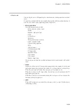
4-12 Isolation Between Input and Output
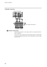
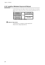
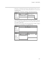
Isolation between inputs and outputs are shown below. In this figure, the solid lines
enclose mutually-isolated sections. Those sections bounded by dashed lines are not iso-
lated.
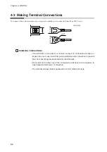
HANDLING PRECAUTIONS
The loader jack is not isolated from internal digital circuits.
When not in use, always replace the cap.
PV input CH1
PV input CH2
Digital
circuit
Control output
Auxiliary output CH1
Loader communication
External switch input
Auxiliary output CH2
Communication
Event output
Memory card input *
* : available on the DCP551E***** model only
4-18