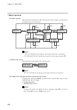


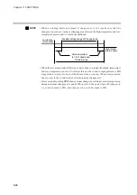

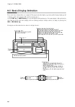


When 100 to 240V AC is applied across terminals (39) and (40) on the DCP551, the display goes on in about 10 sec-
onds and controls and other operations start. When the controller is starting up, the LEDs on the profile display go on
at irregular intervals one after the other starting from top right in clock-wise order until the controller becomes ready
for operation.
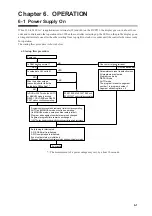
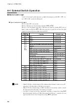
The startup flow procedure is shown below.
●
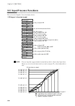
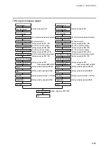
Startup flow procedure
*: The measurement of a power outage may vary by about 10 seconds.
C43
C43
*
!"# $ #%
& '(
)*+$ ,%&*$ ) * )*+
!"# (
+)"
+)"
+)"
%
%
)*+$ $ ,%&*$!"#$ ) *
)*+ !"# (
- . (
. ' (
(
)*+
#%
#
/ /(
" ' 0
%
.1 (
#% & (
& $ (
(
" (
#% $ 2 2 (
(
3("%4 5(
* 5(
)' 5(
- 2 2 (
" .
Chapter 6. OPERATION
6-1 Power Supply On
6-1