


112
────────────────────────────────────────────────────
5.6 Setting the Waveform Display Screen
────────────────────────────────────────────────────
5.6.2 Entering by CH.SET Key
NOTE
Setting the power monitor (when the 9549 FUNCTION UP DISK is
installed)
Waveform display color
Waveform display graph
Zero position
Magnification/compression ratio of voltage axis.
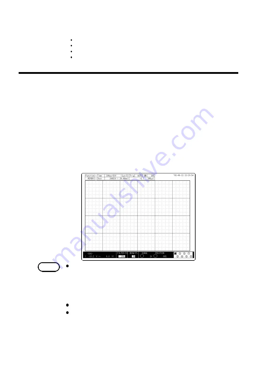
Procedure
1. Press the
DISP
key to display the Waveform display screen.
2. Use the channel keys (
CH1
to
CH8
) to select channels. You can only select
the input modules that are installed.
3. You can set the zero position and the voltage axis range of the channels that
have been selected with the
POSITION
and
RANGE
knobs.
4. You can set the low-pass filter with the
F4
key.
5. You can turn the waveform display ON and OFF with the
F5
key.
6. When setting other channels, select the
CH.SET
key to set them.
7. Pressing any key other than the
F1
to
F10
and the
CH.SET
key returns you to
the Waveform display screen.
Possible settings with the
CH.SET
key:
1. Voltage axis range settings
2. Zero position settings
3. Turning the waveform display ON and OFF
4. Low-pass filter settings
Settings other than those described above are not possible.
Settings made with the
CH.SET
key are also enabled when starting.
The
CH.SET
key is also available to make settings for each channel.
Summary of Contents for MEMORY HiCORDER 8855
Page 2: ......
Page 20: ...xii Chapter Summary...
Page 21: ...1 1 2 3 4 5 6 7 8 9 10 11 12 13 14 A Chapter 1 Product Overview...
Page 28: ...8 1 2 Identification of Controls and Indicators...
Page 116: ...96 4 8 FFT Analysis Function...
Page 117: ...97 1 2 3 4 5 6 7 8 9 10 11 12 13 14 A Chapter 5 Input Channel Settings...
Page 177: ...157 1 2 3 4 5 6 7 8 9 10 11 12 13 14 15 Chapter 8 Search Function...
Page 186: ...166 8 6 Moving Cursors to the Search Points...
Page 205: ...185 10 5 Example of Printer Output Printing the List MEM Example...
Page 263: ......
Page 264: ......


