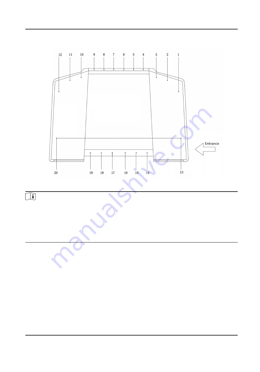
Figure 5-2 IR Modules
Note
●
For details about wiring arrangement, refers to the actual device.
●
If the turnstile contains two lanes, standing at the entrance position, the IR modules on the left
pedestal are the IR sending modules. The IR modules on the right pedestal are the IR receiving
modules. The IR modules on the left side of the middle pedestal are the IR receiving modules,
while the IR modules on the right side of the middle pedestal are the IR sending modules.
●
Safety Instructions can be viewed on the middle panel inside the pedestal.
5.2 Wiring
3 interconnecting cables are contained in the package:
24 VAC Power Interconnecting Cable
The 24 VAC Power Interconnecting Cable of 12AWG is placed inside of the right/middle pedestal
at the exit direction.
Lane Control Interconnecting Cable
DS-K3B631TX Series Swing Barrier User Manual
16
Summary of Contents for DS-K3B631TX Series
Page 1: ...DS K3B631TX Series Swing Barrier User Manual ...
Page 23: ... The dimension is as follows DS K3B631TX Series Swing Barrier User Manual 9 ...
Page 35: ...Figure 5 7 Sub Access Control Board Terminal DS K3B631TX Series Swing Barrier User Manual 21 ...
Page 47: ...Figure 5 22 Remaining Closed DS K3B631TX Series Swing Barrier User Manual 33 ...
Page 174: ...UD30186B ...


