background image

Page A10 


Operations Manual SC-610 


Harmonic Drive AG 

900105 

11/2005


APPENDIX D


Multi - Drop - Applications


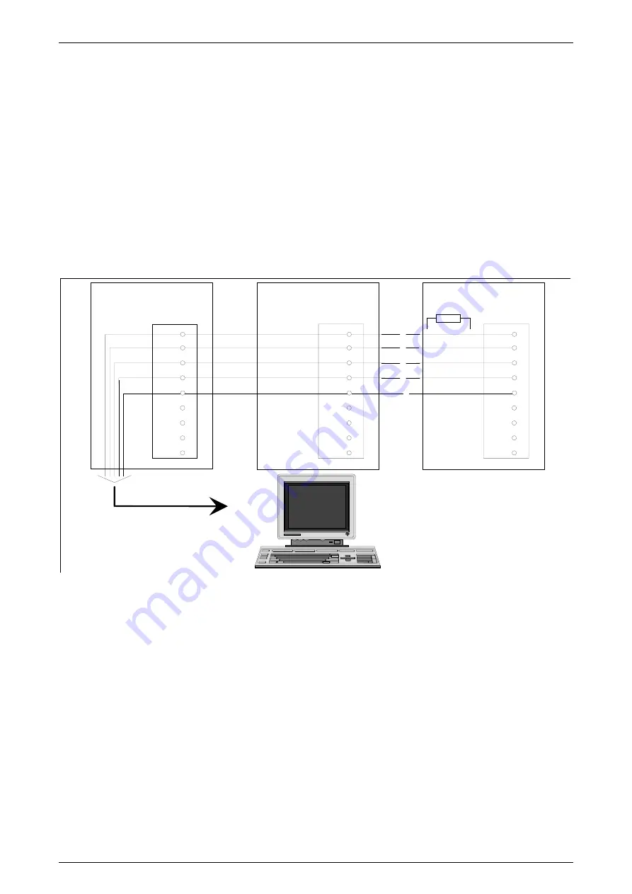
This mode is available setting DIP-switch no. 10 at the front panel of the drive to ON. The wiring 
principle for multi-drop applications is shown below. Each connected drive will also get it´s own 
hardware address. The setting can be done by DIP-switches AS1-4 on the front panel or by using 
the setup software Work Bench v5. 
The picture below shows termination resistors on the last connected drive. The resistor can be 
activated by using DIP-switch AS1.6 and set it to ON-position. 


Multi-drop wiring principle for RS485: 


TX-

TX+

RX+

RX-

DGND

3

7

8

2

5

6

7

8

9

X6

RS485

SC  / A0

SC / A1

SC / An

c/f

Termination Res.

RS485

Interface cable refer
to chapter 4.2.7.

TX-

TX+

RX+

RX-

DGND

3

7

8

2

5

6

7

8

9

X6

RS485

TX-

TX+

RX+

RX-

DGND

3

7

8

2

5

6

7

8

9

X6

RS485


Summary of Contents for SC-610 Series

Page 1: ...Operations Manual AC Servo Controller SC 610 No 900105 11 2005 24 11 2005 FA...

Page 2: ...rmation is subject to change without prior notice Harmonic Drive AG would appreciate notice of any mistakes in the text HARMONIC DRIVE AG owns the copyright to this document which is supplied to custo...

Page 3: ......

Page 4: ...n Resistor Wiring 21 4 2 Control and Signal Wiring 22 4 2 1 Control Inputs 22 4 2 2 Control Outputs 25 4 2 3 Resolver 25 4 2 4 Encoder Output 26 4 2 5 Master Encoder Input 26 4 2 6 Command Input 27 4...

Page 5: ...e The enclosure must protect the control from exposure to excessive or corrosive moisture dust and dirt or abnormal ambient temperatures The exact operating specifications are found in Section 1 of th...

Page 6: ...NG Improper operation of control may cause violent motion of the motor shaft and driven equipment Be certain that unexpected motor shaft movement will not cause injury to personnel or damage to equipm...

Page 7: ...red Caution The safe integration of the drive into a machine system is the responsibility of the machine designer Be sure to comply with the local safety requirements at the place where the machine is...

Page 8: ...applications only It is not meant for use in home appliances medical equipment cars ships or airplanes Before the drive is put into operation please contact your Electric Supply Company for special op...

Page 9: ...ack Hiperface feedback Diagnostic display on front panel Amplifier configuration adjustable via software Software amplifier tuning capability with graphic program Wiring of control inputs and outputs...

Page 10: ...ents or constructions Guidelines for CE Conformity Machine Guideline 89 392 EWG Machine Safety Law EMV Guideline 89 336 EWG EMC Law Low Voltage Guideline 73 23 EWG Machine Safety Law 1 6 Technical Dat...

Page 11: ...x Input Frequency MHz 2 5 quadrature 1 25 Pulse and Direction 1 6 4 2 Hiperface X8 Hiperface Input Unit SC 610 X Signal Sinosoidal Parameter channel RS485 Operating Mode 1024 Sin Cos periods per motor...

Page 12: ...ution at resolver feedback ppr 512 1024 2048 40961 1 factory default The above given signal sequence depends on the connected servo actuator and its feedback system and is specified as follows Actuato...

Page 13: ...of Basic Units mm 67 5 x 173 x 152 5 92 5 x 173 x 152 5 109 x 173 x 152 5 Dimensions for Units with I O Expansion for 256 Positions mm 84 x 173 x 152 5 109 x 173 x 152 5 109 x 173 x 152 5 Weights for...

Page 14: ...nal Unit SC 610 X Input Voltage 15 20 f 50 bis 60Hz VAC Vin 230 115 Nominal 230 115 Maximal 265 130 Minimal 90 90 DC Bus Voltage absolute min max 1 VDC 125 360 at 230 VAC 125 175 at 115 VAC DC Bus Vol...

Page 15: ...if 24V is switched on 2 2 Electrical Installation The wiring fusing and grounding must be in accordance to the national electrical code and any local codes Use of motor thermo switch It is recommende...

Page 16: ...the unit is covered during installation to prevent particles from falling into the unit Mount all drives vertical Connector X1 to the top Use the controller in stationary ground based applications onl...

Page 17: ...6 1 CHA 2 CHB 3 CHC 4 N A 5 DGND 6 CHA 7 CHB 8 CHC 9 N A X7 1 N A 2 R X 3 TX 4 N A 5 D G ND 6 N A 7 R TS 8 C TS 9 8VKeyp N A RX TX N A DGND N A TX RX 8V Keyp RS232 RS485 X6 5 min Dangerous to acciden...

Page 18: ...Resolver 5 min Dangerous to accidental contact up to 5 minutes after switching off the main supply OL Adjustment See Manual Use Copper Conductors only Encoder Output 1 CMD 2 CMD 3 AGND 4 FAULT RELAY 5...

Page 19: ...3 Interconnection Diagram TTL Encoder Control Signals Digital I O s Content of delivery mating connectors to X1 X3 and X8 Overview of mating connectors X1 10 pole female X6 9 pole female UNC X3 20 po...

Page 20: ...Operations Manual SC 610 Page 17 Harmonic Drive AG 900105 11 2005 3 4 Connector Configuration I O Expansion for 256 Positions Caution 1 20...

Page 21: ...ltage The power supply module consists of rectification smoothing regeneration circuit and surge current protection 2 2 2 4 PE L N PE L1 N 1 2 3 5 L1 N X1 1 X1 2 X1 3 1 Autotransfomer 2 Isolating tran...

Page 22: ...otected from high frequency interferences which could enter via the mains cable noise immunity and vice versa the mains cable may not transmit interferences from the electronic systems to the adjoinin...

Page 23: ...or Cables All cables have to be screened The maximum cable length is 25m 4 1 4 24VDC Connection optional A 24V stand by option is available for all drives With this option the control circuits are sup...

Page 24: ...current A Harmonic Drive Order No 44 56 230 7 700889 100 39 230 10 701121 1 Duty cycle 2 at T 120s The generation resistor is not automatically included in the delivery The generation resistor must be...

Page 25: ...Clockwise direction of rotation enabled Clockwise direction of rotation disabled DIN 1 CCWLimit1 X3 11 Counter clockwise direction of rotation enabled or position selection Counterclockwise dir of rot...

Page 26: ...the positioning after the quit input has been reset to zero DIN x There are up to 4 machine inputs available Inputs X3 16 DIN 6 and X3 17 DIN 7 can either be used together with the PLC program default...

Page 27: ...ing to the external control input power sup ply The switch will be linked between the control input X3 x and the external power supply Vext The ground return GNDext is permanently wired with CREF X3 7...

Page 28: ...output 0 logical 0 DOUT 1 X3 19 Digital output 1 logical 1 Digital output 1 logical 0 DOUT 2 DrOK X3 20 Digital output 2 active no fault Digital output 2 not active drive fault More about control outp...

Page 29: ...red COS X8 7 yellow black SIN X8 3 pink yellow SIN X8 8 grey grey All cables have to be screened 3x 2x0 14mm2 4 2 4 Encoder Output The controller has an encoder output X7 which can be used for positio...

Page 30: ...eel encoder The ratio between incoming encoder signals and the motor speed is configurable via software Wiring of the encoder input The connector X9 must be wired according to the interconnection diag...

Page 31: ...wn below A RS232 RS232 is the standard interface CAUTION The serial connector on the SC610 X6 can be configured as either RS232 or RS422 RS485 Pin 9 is used to carry 8V for powering certain keypad per...

Page 32: ...n Power Autotransformer Isolating transformer 1 phase connection see also chapter 4 1 1 2 Fuses see also chapter 4 1 1 3 Main Filter see also chapter 4 1 2 and appendix A 4 Power cable not available f...

Page 33: ...in order to achieve the wiring according to the EMC regulations 1 1 CW Limit and CCW Limit Please note that servo axes incorporating Harmonic Drive gears i e FHA CHA FFA and RS C series will be effect...

Page 34: ...ix A in order to achieve the wiring according to the EMC regulations CW Limit and CCW Limit Please note that servo axes incorporating Harmonic Drive gears i e FHA CHA FFA and RS series will be effecte...

Page 35: ...x A in order to achieve the wiring according to the EMC regulations CW Limit and CCW Limit Please note that servo axes incorporating Harmonic Drive gears i e FHA CHA FFA and RS C series will be effect...

Page 36: ...in order to achieve the wiring according to the EMC regulations 1 1 CW Limit and CCW Limit Please note that servo axes incorporating Harmonic Drive gears i e FHA CHA FFA and RS C series will be effect...

Page 37: ...ust be supplied with an external voltage source 13 The Control cable is not available from Harmonic Drive Drawing shows the wiring principle only Can be one or more cables NOTE DGND and AGND are inter...

Page 38: ...g the DIP switch on the card as follows AS1 1 AS1 2 AS1 3 AS1 4 Card Address Node number OFF OFF OFF OFF Will be determined by Mint Keyword Node OFF OFF OFF ON 1 OFF OFF ON OFF 2 OFF OFF ON ON 3 OFF O...

Page 39: ...urpose of the offset compensation is to cancel offsets on the line Therefore it is important to set the analog command to zero It is recommended to leave this switch at OFF during normal operation AS1...

Page 40: ...the LED will show the following state LED DB ON OFF After power on procedure the monitor will show the final state Status Status will show only decimal point lower right corner must be OFF If status...

Page 41: ...monitor shows a check ENABLE input X3 9 and DIP switch AS 1 8 If the motor shaft accelerates turn off the power immediately and check the motor and measuring system If the decimal point on the monitor...

Page 42: ...errors in any 500 servo tick period will cause the drive to trip This error indicates loss of encoder resolver feedback and may indicate that the feedback cable has become detached or one of the sign...

Page 43: ...See the Mint keywords MOVEA and MOVER Preset positions The drive is performing a linear move This motion has been triggered from a Preset move table Stop A STOP command has been issued or the stop inp...

Page 44: ...not valid for DIN4 and DIN5 Function Signal PIN Hardware Enable DIN 0 DIN 1 DIN 2 DIN 3 DIN 6 DIN 7 Ground Return ENABLE CWLimit position select CCWLimit position select HOLD QUIT FRESET Position Sel...

Page 45: ...Delay time Td 60 s max current at 24V I 5 2mA Advices for wiring DIN4 and DIN5 Shielded and twisted pair cables have to be used in order to avoid disturbance caused by electic interference Mechanical...

Page 46: ...OUT 2 Drive OK Customer Interface Voltage Ground Return FAULT REL FAULT REL __________ General Purpose General Purpose DrOK CIV CGND 4 5 _____ 18 19 20 6 8 Contact is closed if system works correct UA...

Page 47: ...unction Signal PIN Hardware Reference Signal REF REF 1 6 Signal waveform sinusoidal f 7 2 8 0kHz 17 0Vpp 5 0 0 4 VDC Ipeak 0 2A short circuit proof Resolver Signals Connector X8 Function Signal PIN Ha...

Page 48: ...r X8 Function Signal PIN Hardware Parameter Parameter Cosine CosReference Sinus SinReference _____________ Power supply Power supply Clock Clock Reference Reference _____________ _ Ground return Groun...

Page 49: ...C ______________ Hall Input U and U Hall Input V and V Hall Input W and W ______________ Power Supply Reference CHA CHA CHB CHB CHC CHC ________ _ SYNC_U SYNC_U SYNC_V SYNC_V SYNC_W SYNC_W ________ _...

Page 50: ...nput 8 logical 0 DIN 9 X12 14 Digital Input 9 logical 1 Digital Input 9 logical 0 DIN 10 X12 2 Digital Input 10 logical 1 Digital Input 10 logical 0 DIN 11 X12 15 Digital Input 11 logical 1 Digital In...

Page 51: ...tput 5 logical 1 Digital Output 5 logical 0 DOUT 6 X12 23 Digital Output 6 logical 1 Digital Output 6 logical 0 DOUT 7 X12 10 Digital Output 7 logical 1 Digital Output 7 logical 0 USR X12 25 USR GND X...

Page 52: ...Operations Manual SC 610 Page A1 Harmonic Drive AG 900105 11 2005 APPENDIX...

Page 53: ...s should be placed with an earthing strap at a central grounding point 1 B There should be a spatial separation between power wiring motor and power cable and control wiring Avoid interaction space C...

Page 54: ...W2 L L L L Rx L Rx L 24 V 0V 5min Caution Dan ger ous to ac cident al con tact up to 5 minu tes aft er switching o ff th e ma in su pply Reg loa d X10 X1 X2 X3 X4 X5 X6 X7 X8 X9 Monitor Ready U1 V1 W1...

Page 55: ...arealy conducted to the cabinet back plane p EMC FILTER The EMI or main filter should be mounted next to the power supply For the connection to and from the main filter screened cables should be used...

Page 56: ...nual SC 610 Page A5 Harmonic Drive AG 900105 11 2005 APPENDIX B DIMENSIONS A Drive Standard Series without I O Expansion Values in refer to the controllers with additional binary inputs 7 5A Unit 5A U...

Page 57: ...llowing main filters FN 2070 06 06 FN 2070 10 06 FN 2070 12 06 not scaled dimensions in mm Dimensions in mm FN 2070 6 06 FN 2070 10 06 FN 2070 12 06 A 113 5 156 B 57 5 C 46 6 D 94 130 5 E 103 143 F 25...

Page 58: ...r torque to high 3 Amplifier ambient temperatur to high 0 Watchdog When the display shows a 0 a watchdog timeout occurred in the processor Drive comms watchdog Interprocessor failure Clear the error L...

Page 59: ...The catalog number indicating the type of SC Drive you have Use the Help about menu item in WorkBench v5 to view details about your system The catalog and specification numbers of the motor that you a...

Page 60: ...set and the drive disables when tuning the gains Set FOLERRORMODE to zero to ignore the following error while tuning the gains I get a Software limit error AXISERROR bits 3 or 4 set and the drive disa...

Page 61: ...ting can be done by DIP switches AS1 4 on the front panel or by using the setup software Work Bench v5 The picture below shows termination resistors on the last connected drive The resistor can be act...

Page 62: ...ments Operating System Windows 2000 Recommended Windows 98 Windows ME Windows 2000 SP4 Windows XP SP1 B Installation To install the WorkBench software on your computer s hard disk please follow the se...

Page 63: ...ent of Inertia of the Motor without gear 2 System Parameters NMAX Maximum motor speed at 10V demand input Enc Res Number of encoder counts per one motor revolution Power Supply Amplifier power supply...

Page 64: ...Operations Manual SC 610 Page A13 Harmonic Drive AG 900105 11 2005 APPENDIX G...

Page 65: ...Page A14 Operations Manual SC 610 Harmonic Drive AG 900105 11 2005 APPENDIX H...

Page 66: ...Operations Manual SC 610 Page A15 Harmonic Drive AG 900105 11 2005 APPENDIX I...

Page 67: ...Page A16 Operations Manual SC 610 Harmonic Drive AG 900105 11 2005 APPENDIX J...

Page 68: ...Operations Manual SC 610 Page A17 Harmonic Drive AG 900105 11 2005 APPENDIX K...

Page 69: ......

Reviews: