


3 - Description
19
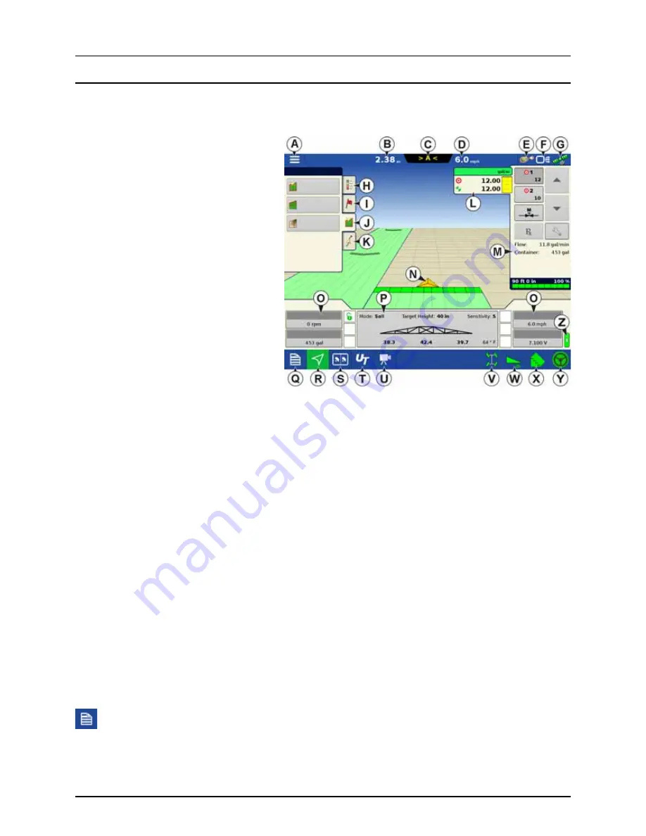
Map Screen
Work Screen
The appearance of the Map screen varies, depending upon which operation you are performing, and your specific operating
configuration.
A.
Menu
B.
Area Covered
C.
Path Indicator
D.
Speed
E.
AgFiniti Status Indicator
F.
Diagnostics Status Indicator
G.
GNSS Satellite Status Indicator
H.
Legends Tab
I.
Markers Tab
J.
Field Operations Tab
K.
Guidance Tab
L.
Product Tab
M.
Product Control Toolbox
N.
Vehicle Icon
O.
Equipment Tab
P.
AutoTerrain/AutoHeight Settings
Q.
Summary Screen
R.
Map Views
S.
Split-Screen (HC 9600 only)
T.
Universal Terminal
U.
Video Button
V.
4-Wheel Steer Logging Button
W.
AutoTerrain/AutoHeight ON/OFF
X.
AutoSectionControl (Autoswath)
Y.
AutoSteer Button
Z.
Main ON/OFF Switch Status
The task bar displays function buttons to the left (Q to U), and status indicators to the right (V to Y) relating to various
functions of the display. These buttons are shown in front of a green background when function is enabled or you are at that
screen; otherwise they are shown in front of a blue background.
Buttons and indicators are explained in the following:
Equipment Tabs
Different Display Items can be selected by pressing the Equipment tabs (O).
Summary Screen
Pressing the Summary screen button takes you to the Summary Report screen. See “Summary Report” on page 171.
8.99
ac
Field
Boundary
Spray Pump
Wheel Speed
Voltage
Water
Flow:
Container:
Sensitivity:
Target Height:
Soil
Mode:
Tank Volume
Headlands
Topography
Summary of Contents for HC 9600
Page 2: ......
Page 4: ......
Page 12: ...2 Safety Notes 10...
Page 32: ...3 Description 30...
Page 182: ...5 Operation 180...
Page 184: ...6 Maintenance 182...
Page 198: ...7 Fault finding 196...
Page 202: ...8 Technical specifications 200...
Page 210: ...Index 208...
Page 211: ......


