background image

4 - System setup

46

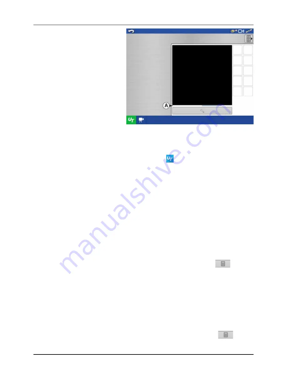
When an ISOBUS compliant implement is 

connected to the display for the first time, Status 

Bar (A) appears while Object Pool is in the process 

of loading.

μ

ATTENTION! Once loaded, object pools are 

stored in the display memory.

ISOBUS Settings Screen

Other options to be set are:

Enable Universal Terminal

(Mandatory setting)

Assign Universal Terminal functions to ISO compatible inputs.
Once a Universal Terminal has been enabled 

 will appear in the task bar. Toggle between 

the Universal Terminal run screen and other display functions by pressing the UT button.

÷

NOTE! Always enable this when connected to a HARDI® ISOBUS system.

Broadcast Display Speed 
(ISO GBSD)

Checking this box allows speed source currently being utilized by the display to be broadcast 

over the ISOBUS to the implement ECU.

Broadcast GPS (J1939)

Checking this box allows GPS data being supplied by the GPS receiver to be broadcast over the 

ISOBUS to the implement ECU.
Do not check this when using the sprayer speed sensor - see also “Speed Input Settings” on 

page 89.

Auxiliary Module Support

Allows non-HARDI® Auxiliary Module to be used with ISOBUS ECU’s that support AUX-N 

auxiliary functions.
Not used for normally setup HARDI® sprayers.

Universal Terminal 
Functional Instance

Always set to 0 except when there are multiple UT’s on the ISOBUS. Use 

 to change 

instance. Reboot Display.

Enable Task Controller

(Mandatory setting)

Checking this box allows the HC 8600/HC 9600 to communicate with the sprayer’s JobCom 

computer and thereby use its functions, e.g. Automatic Swath Control.
If having more than one screen, Automatic Swath Control can only run on one of these 

screens. This screen is selected by setting the Task Controller Function Instance value.

÷

NOTE! Always enable this when connected to a HARDI® ISOBUS system. Otherwise it will 

give an error message when starting a spray job in the working screen on the HC 

8600/9600.

Task Controller Function 
Instance

Always set to 0 except when there are multiple screens on the ISOBUS. Use 

 to change 

instance. Reboot Display.

Summary of Contents for HC 9600

Page 1: ...The Sprayer Operator s Manual CONTROLLER HC 8600 9600 Instruction book SW 1 X 67025303 Version 1 00 US 03 2017...

Page 2: ......

Page 3: ...W 1 X 67025303 Version 1 00 US 03 2017 HARDI reserves the right to make changes in design material or specification without notice thereof HARDI and other product names are registered trademarks of HA...

Page 4: ......

Page 5: ...dicators 18 Map Screen 19 Work Screen 19 Map Toolbox 22 Legend Settings 22 Map Options 23 Map Shift 24 Split Screen Map 26 Markers tab 27 Video 27 AgFiniti 28 General Info 28 AgFiniti Mobile Connectio...

Page 6: ...s 95 TerraStar Settings 95 RTK External Settings 96 RTK Settings NTRIP 96 RTK Settings 400 MHz 98 RTK Settings 900 MHz 98 Upgrade Receiver 99 Serial Port Settings 99 Lightbar Settings 101 Setup 101 Gu...

Page 7: ...ta Transfer screen 148 Display Backups 148 Upgrade Firmware 149 Importing Logged Data 149 Exporting Logged Data 150 Manual Sync 150 5 Operation Map Screen 151 Configuration Setup Screen 151 Mapping To...

Page 8: ...d 187 ISOBUS Configuration Mismatch 188 GPS 189 GPS Information 189 GPS Information General Tab 189 GPS Messages 191 Satellite Plot 192 GPS Information 193 8 Technical specifications Specifications 19...

Page 9: ...s We feel that you our customer are the best suited to answer that question for your operation Either way you decide and we will try and help make it happen for you Our broad spectrum of product offer...

Page 10: ...Yes Yes AutoSectionControl AutoSwath Yes Yes Headlands Yes Yes Multiple Product Control Yes Yes Camera Support 4 4 AgFiniti Mobile Yes Yes USB Port 1 2 Guidance Steering Lightbar Guidance Yes Yes Mec...

Page 11: ...DI dealer for further explanation before using the equipment Keep children away from the equipment Press the keys with the underside of your finger Avoid using your fingernail Local law may demand tha...

Page 12: ...2 Safety Notes 10...

Page 13: ...result in an impairment of the safety features of this product System Uses Manual Guidance AutoTerrain AutoHeight UC5 Hydraulic automated steering Video Camera Inputs Mapping tillage operations Mappi...

Page 14: ...Reset switch is used for turning the display on and off in installations where the system is connected to a continuous power supply If the display ever stops responding the manual power switch may be...

Page 15: ...Touch Screen Here are a few key things to remember if you are new to using a touch screen device Do not use any sharp objects for running the touch screen device this could result in damage to the dis...

Page 16: ...to view other maps If zooming in far enough you should begin to see row by row data on applicable fields Tap to Zoom By tapping on the map you can quickly control the zoom level of your map Quickly do...

Page 17: ...the system An on screen Keyboard is made available when appropriate for use during all setup processes Press the button to access the on screen text entry screen An on screen Numeric Keypad is made av...

Page 18: ...e single display if this is the only display that is getting setup Multiple Display Use multiple display if there is more than one display in the operation and the plan is to share management data bet...

Page 19: ...tillage Planting Create configuration or start operation specific to planting Application Create configuration or start operation specific to application Harvest Create configuration or start operatio...

Page 20: ...ipment Operating Configuration You can access Configuration Setup by pressing or pressing an app specific to a field operation Product setup Start Field Operation Status Indicators Status Indicators a...

Page 21: ...errain AutoHeight ON OFF X AutoSectionControl Autoswath Y AutoSteer Button Z Main ON OFF Switch Status The task bar displays function buttons to the left Q to U and status indicators to the right V to...

Page 22: ...s button repeatedly cycles through the video inputs NOTE For more information on the Video screen see Video on page 27 Activates logging of 4 wheel steering for AutoSectionControl AutoSwath ON AutoSwa...

Page 23: ...en Zoomed Out This gold colored triangle indicates the display is in zoom to extent mode When in zoom to extent mode the vehicle implement does not appear but logged data will still populate on the ma...

Page 24: ...ranges as they appear on the map screen by using the buttons described below Average The Average button changes the average rate for the legend Press to specify the average of the ranges shown on the...

Page 25: ...or clear map Press the Legend Setup and the Map Options screen appears Clear Map Permanently removes on screen map from the active field operation but the log data will still be exported to the USB dr...

Page 26: ...tended period of time the reference point can be used upon returning to the field operation Enable Map Shift With the map shift option checked the map shift icon will become available when in full scr...

Page 27: ...current position 8 Any time a reference point or shift needs cleared it can be accomplished via Map Shift Options Map Shift Needed Shifting Map Map Shift Options Set saves a reference point Shift move...

Page 28: ...elected individually from the legend drop down Map views can be changed by tapping anywhere in the center of the left right side map then choosing from one of the views buttons A Follow View Sets the...

Page 29: ...when enabled in the Console Setup menu see Display Button on page 84 Video button Camera is available from the Home or Map screen Press video button and theVideo screen appears Brightness Press to in...

Page 30: ...niti Mobile Connection Types Display Access Point Mode This connection type turns your HC 8600 9600 display into a wireless access point that all compatible iPads can connect to When using this connec...

Page 31: ...use the backup if one is available Manual Speed If both of the sources are unavailable manual speed can be used in order for the control channel to provide application Manual speed setting is for use...

Page 32: ...3 Description 30...

Page 33: ...itted so the ISOBUS system cabling is routed and secured without interfering with existing machine controls WARNING If drilling holes is required during the mounting process care must be taken to ensu...

Page 34: ...U Power J03 IBBC Relay Module P02 IBBC Relay Module F01 Fuse 5A Blade style J06 Battery power D 26040500 4002825 ISOBUS Termination Assembly J02 ISOBUS J01 Active terminator F 26040600 4002827 16 ISOB...

Page 35: ...0 1 Power display guidance J04 Power 5A J06 Power 15A J09 Battery ground J10 Battery power J01 Fuse 5A blade style J03 Fuse 15A blade style N 26069500 4004667 1 ISOBUS Adapter P01 Display cable J07 EC...

Page 36: ...Power 5A J06 Power 15A J09 Battery ground J10 Battery power J01 Fuse 5A blade style J03 Fuse 15A blade style M 26069900 4004668 1 ISOBUS Joystick Tee cable J01 ISO CAN Out P01 ISO CAN In P02 Grip Conn...

Page 37: ...e Unlock Display Features NOTE Using the Restore backup option is not the proper method to get multiple displays set up to be the same Use the AGSETUP file It is acceptable to complete the initial set...

Page 38: ...nits can also be selected but this book covers Imperial units B Press to confirm 3 Set Time and Date A Press to select Time Zone B Press to set Time and Date C Press to confirm Display Setup Select La...

Page 39: ...ne Integra Versa Compass or HC 9600 HC8500 in your operation Select Multiple Displays to share setup items between Integra Versa Compass and HC 9600 HC8500 displays Single Display Multiple Display Dis...

Page 40: ...ress to acceptthe setup andreturn to Home screen Select New Setup to perform all setup through the display user interface Select Import Setup to select an AgSetup file to import setup items from your...

Page 41: ...tton B Press to continue Display Setup Review Import Management Grower Farm Field Allegon County New Modified Conflicting Resolved Seasons 2016 Crop Products Configuration Display Setup Set Owner Disp...

Page 42: ...play to import into additional displays with version 3 0 or higher Select Additional Display to import setup items from an AgSetup file from an existing display First Display Additional Display Displa...

Page 43: ...isplay user interface Select Import Setup to select an AgSetup file to import setup items from your computer New Setup Import Setup Display Setup Select New or Import Display Setup Select Ag Setup Fil...

Page 44: ...quipment items will be imported to the additional displays Select First Display to export an AgSetup file from this display to import into additional displays with version 3 0 or higher Select Additio...

Page 45: ...ial number _nickname The file will include a date and have the agsetup suffix A Select desired setup file from directory B Press to continue Highlight item with conflict Press Data Transfer Import Fil...

Page 46: ...on See Management button on page 74 Equipment Operating Configuration You can access Configuration Setup by pressing the Setup wrench button C on the Home screen For more information see Equipment Set...

Page 47: ...Working Set One or more ISOBUS modules that control an implement s functionality Working Set Master WSM Main module responsible for coordinating all communication between the UT and the Working Set in...

Page 48: ...BUS to the implement ECU Do not check this when using the sprayer speed sensor see also Speed Input Settings on page 89 Auxiliary Module Support Allows non HARDI Auxiliary Module to be used with ISOBU...

Page 49: ...signment Assign implement functions to ISO compatible inputs Clear Universal Terminal Allows operator to clear the Object Pools sent to the display from the implementWSM After the object pools have be...

Page 50: ...oller and JobCom C2C module for the changes to take effect Cycle power to do this Begin Configuration for your sprayer type Sprayer Types The following configuration is split into two parts depending...

Page 51: ...t Create a tillage operating configuration for coverage logging and guidance only operations Create a liquid and granular application or strip till operating configuration harvest grain yield monitori...

Page 52: ...he tractor to the following locations Rear Drawbar for a trailer sprayer Rear Lift Arms for a lift sprayer ATTENTION The option Front Lift Arms is not used for HARDI sprayers Trailer as example A Choo...

Page 53: ...s to type in the measured value for the GPS Front Back Offset from the vehicle Vehicle Wizard Vehicle Name Enter Vehicle Name JD 4630 Operating Configuration Wizard Vehicle Select Vehicle JD 4630 Offs...

Page 54: ...tion Vehicle Offsets JD 4630 Antenna Hitch Enter Distance from Vehicle References to the Antenna Antenna Location from Rear Axle Antenna Location from Centerline Antenna Height from Ground In Front Le...

Page 55: ...e button 16 Implement Information A Press the Make to type in the implement name B Press the Model to type in the implement model C Press to confirm Operating Configuration Wizard Vehicle Select Vehic...

Page 56: ...e correct NOTE If this screen appears blank no text highlighted with blue no data could be obtained If the JobCom is not powered ON then press to cancel the setup Power On the JobCom and continue from...

Page 57: ...me Implement Wizard Additional Devices Norac UC5 OptRx Crop Sensor Crop Sensor Settings Sensing Width Number of Sensors Swath Offsets Note Sensing Width should typically be set to the same width as th...

Page 58: ...ATTENTION For additional information see Speed Input Settings on page 89 25 Hardi is now selected as Primary Source ATTENTION No other source can be selected when Hardi is selected as primary source...

Page 59: ...ting Configuration Wizard Configuration Name Suggested Name for Configuration JD 6430 Hardi Commander Configuration Setup Vehicle JD 4630 Vehicle Offsets Norac UC5 Speed Input Auxiliary Input Automati...

Page 60: ...e area This prevents the possibility of overlaps User Defined Allows you to choose what percentage of the implement section is within the coverage area before that section turns off For example if you...

Page 61: ...sections are turned off Hardi default value 0 5 second Press to confirm 32 Overview of Configuration Setup with a Trailed sprayer as example Vehicle JD 4630 Implement Hardi Commander Device Hardi Con...

Page 62: ...Setup Product Equipment Equipment Name Tillage Planting Create a planting operating configuration Application Harvest Create a tillage operating configuration for coverage logging and guidance only o...

Page 63: ...be used when spraying B Press to confirm ATTENTION Checking the All Wheel Steer optionactivatesloggingof4wheelsteering for AutoSectionControl Operating Configuration Wizard Vehicle Select Vehicle Veh...

Page 64: ...ng this wizard See Before Setup on page 48 Press to confirm selection 9 Additional devices A Press Norac UC5 button to enable the use of AutoTerrain AutoHeight B Press to continue ATTENTION If the Nor...

Page 65: ...line E Press to enter Antenna Height from Ground F Press Steering to continue with Steering Type selection Vehicle Wizard Vehicle Name Enter Vehicle Name ALPHA evo Operating Configuration Wizard Vehi...

Page 66: ...option must be selected as backup source ATTENTION For additional information see Speed Input Settings on page 89 Vehicle Offsets ALPHA evo Antenna Steering All Wheels Steering Type Operating Configu...

Page 67: ...election 18 Press Automatic Swath Control to edit the configuration Operating Configuration Wizard Speed Source Primary Source Operating Configuration Wizard Configuration Name Suggested Name for Conf...

Page 68: ...nimize Overlap Turns off the implement section when that section first enters your coverage area This prevents the possibility of overlaps User Defined Allows you to choose what percentage of the impl...

Page 69: ...ystem when the sections are turned off Press to confirm 21 Overview of Configuration Setup Vehicle Saritor 5000 Device Hardi Container 1300 Device Boom Height ATTENTION A Self Propelled sprayer will h...

Page 70: ...er 3 Press the drop down menu to select Carrier as Product Type Configuration Setup Configuration Product Equipment Add Product Seed Variety Application Product Mix Blend Harvest Product Create a seed...

Page 71: ...to confirm the selection 6 Product Name A Press to change Product Name B Press to confirm Product Name NOTE This step is not possible when setting up water as Carrier Product Setup Wizard Product Typ...

Page 72: ...Setup Guide has been completed the controller is ready for use in the field Refer to Setup Event on page 156 for instructions on how to begin a field operation Configuration Setup Configuration Produ...

Page 73: ...page 72 as well as Configuration Setup Screen on page 151 Management button Press to access and edit Grower Farm Field and Operator information For more information see Management button on page 74 GP...

Page 74: ...t on the left side of the screen When you highlight the configuration the equipment in the configuration are listed in the box on the right side of the screen NOTE Information regarding configurations...

Page 75: ...about the product appears on the right side of the screen Specific planting and application product information can be viewed in those respective chapters Press to rename the product Press to remove a...

Page 76: ...rm and Field In the display farms are subdivided into fields You can associate Field names with a particular Grower If the display will be used for multiple Growers enter each Grower business name and...

Page 77: ...FSA Number Refers to the U S Farm Service Agency s four digit number assigned to every field FSA Area Refers to tillable acres as established by the FSA Clear Bounds button Press to center the map on...

Page 78: ...lds and boundaries at once with an AGSETUP file For more information on AGSETUP files see AGSETUP on page 198 Press to complete the import process To export a boundary to the USB drive highlight the c...

Page 79: ...in the Summary list box to the active season Season Reminder button Press to set the date that the system will prompt the operator to create a new season Press to remove a season Users tab User tab al...

Page 80: ...tor or Manager can select either none or both Operators Have full or limited access No access to USB or Setup options unless also set as a Manager Can import from USB from Map Screen RX patterns bound...

Page 81: ...n Pan Zoom controls Legend Toolbox Marks Toolbox Boundary Toolbox Guidance Toolbox Minimize Toolbox Each individual guidance pattern Ability to remove guidance patterns Display uses Traditional mode w...

Page 82: ...continue or start new operation when operators change Full Permissions Home Screen Summary screen button is accessible Setup and Data Transfer are locked A manager can access these buttons by pressin...

Page 83: ...from drop down menu Press 3 Enter password Press Password gives complete access to the setup menus Configurations Settings Grower management GPS settings Display settings Do not have to be a Manager...

Page 84: ...sword gives complete access to the USB functions Networking AgFiniti Login Import export AgSetup files Export data Upgrade firmware Advanced options Advanced Options with USB Ability to create restore...

Page 85: ...d What if a customer doesn t want to risk forgetting passwords and generating new ones A display does not need to be locked with a password The display can be operated without passwords Operators can...

Page 86: ...month date and year To make these changes effective press NOTE The display will then shut down immediately If you do not want to shut the display down press the Close Red X button however the time dat...

Page 87: ...S Settings Enables Universal Terminal and Task Controller See Enable Universal Terminal and Task Controller on page 45 for explanation of settings Display tab The Display tab contains functionality fo...

Page 88: ...ck codes Press to enter the unlock code and press to enable the feature NOTE Once a feature is unlocked that feature remains with that display and cannot be transferred to another ATTENTION Features u...

Page 89: ...off immediately preceding shutdown If you wish the display to remain powered up for a longer period of time touch the display to restart the Key Switch Standby countdown About button Displays product...

Page 90: ...es module firmware that you may not be running Import Imports any firmware stored on the USB drive into the display memory Direct Upgrade Upgrades an individual module directly from the USB NOTE Press...

Page 91: ...lable Hardi Display GPS Auxiliary Device Manual Speed Trailer sprayer with SafeTrack IntelliTrack Must always use Hardi as speed source as the steering system cannot use GPS as speed source Not used N...

Page 92: ...coverage area This prevents the possibility of skips Minimize Overlap Turns off the implement section when that section first enters your coverage area This prevents the possibility of overlaps User...

Page 93: ...enter the vertical height of the antenna above the ground NOTE Accuracy when measuring for a specific setting is essential to ensure proper machine performance Hitch Settings tab The Hitch Tab allows...

Page 94: ...etric booms As HARDI booms areneverasymmetric thisoptionmustbeset to 0 ft Left or Right selection does not matter Boom Height tab Forward Backward Distance from Hitch Set distance between the hitch ey...

Page 95: ...ENTION Pressing next to the Receiver options opens the selected receiver s specific settings Populated settings vary from one receiver model to the next Operator Presence Alarm The Operator Presence A...

Page 96: ...then transition back to the higher accuracy source eliminating position jumps Press to enable StableLoc Error Limit RTK TerraStar only When using StableLoc select the error limit at which the system w...

Page 97: ...the TerraStar solution as converged when the horizontal standard deviation reaches the Convergence Threshold setting Relaxing the convergence threshold shortens the time before a TerraStar solution is...

Page 98: ...Streams Disconnect Connect to the NTRIP Network Info see Info button on page 97 Cellular IP Address indicates a connection to the Internet Modem Status Receiver GPS 6500 Serial General Differential So...

Page 99: ...provider for this information Info button Stream Format Format Details Navigation System Network Authentication The information shown on this screen is provided by the NTRIP Network Server NTRIP Serv...

Page 100: ...frequency and press button to make selected frequency active Press button to add a Channel Selectchannelandpressbutton to delete selected channel Selectchannelandpressbutton to make selected channel...

Page 101: ...10 Hz minimum NMEA Messages These checkboxes represent various communication protocols or formats that have been set by the National Marine Electronics Association NMEA and used in information string...

Page 102: ...precision of the GGA message for connection to legacy equipment GGA Position Gives increased precision to the GGA message Most new displays require this turned on Receiver GPS 6500 Serial Port B GPS...

Page 103: ...The number 1 is the dimmest setting and 10 is the brightest Default setting is 5 Guidance Tab on Mapping Toolbox The Guidance Tab on the Mapping Toolbox allows you to create a new pattern load an exi...

Page 104: ...eet 30 meters Pause Press to pause path during path creation Resume Press to resume path during path creation Cancel Press to cancel path during path creation Press to mark point B The AB line appears...

Page 105: ...t pattern Implement Width from Implement Setup Guidance Width input box Press to accept You will automatically return to the Map screen Create AB line using 2 points Press to mark point A A green ball...

Page 106: ...irst time For more information see AutoSave on page 110 New Pattern Identical Curve Use the Identical Curve pattern to follow gentle contours in the field This pattern provides guidance based on the o...

Page 107: ...ved swaths This makes it possible to get LED guidance back onto the swath if the vehicle drives past the end of a swath The extended swath lines do not appear on screen New Pattern Pivot Use the Cente...

Page 108: ...ts the field edge as the distance and direction in relation to the AB Line created In the Pivot Field Edge Distance portion of the window enter the distance in feet and inches Shift By Rows This sets...

Page 109: ...tween any available pattern within SmartPath to choose the appropriate one Select SmartPath System defaults pattern type to last used Press the pattern icon to select a different pattern Implement Wid...

Page 110: ...ine parallel to your previously driven pass As you continue using the SmartPath the map screen will display three lines A The Base Path Appearsasablackline istheinitialSmartPath that you created on th...

Page 111: ...hold settings on the Smart Tab of the Guidance Option screen SmartPath Guidance Options SmartPath only creates a SmartPath pass when you are logging data in the field However you have the option of us...

Page 112: ...will be the closest to current GPS location Check the box to show all patterns Import Pattern Display informs you when file has been successfully copied Export Pattern Display informs you when file h...

Page 113: ...the current field Reset Pattern If you have been using an already saved pattern and wish to switch over to a different pattern in the same field you can use the Reset Pattern feature by following the...

Page 114: ...Pattern Setting dialogue appears and allows the user to select the Guidance Width and any Shift that needs to be applied to each Pattern within the Pattern Group User will also have the option to loa...

Page 115: ...lace where you paused appears on the Map screen as a yellow ball NOTE You can pause a pattern even if you have not set the B point yet If you do so the message in the lightbar will read Need B If you...

Page 116: ...essive press of the left or right arrows buttons on the Guidance Tab To clear out the adjustment and go to the original position press Clear Nudge Screen shows Small and Large increment settings for S...

Page 117: ...ers onto the desired steering path The ideal setting allows the system to take the shortest route without excessively sharp or sudden movements of the vehicle Steering Response Controls the oscillatio...

Page 118: ...osite direction of the indicator lights on the lightbar External Lightbar LED Brightness Ifapplicable press toenter in a number specifying the brightness of the LED lights on the optional L160 externa...

Page 119: ...move the placement of the tramline by one pass left or right Use the toggle button to switch menu between Tramline and Nudge on the Mapping Toolbox An audible warning is sounded to alert the operator...

Page 120: ...by pressing 5 Press to enter a unique name for the product Created product should appear under the Application heading located on the Product tab of the Configuration Setup screen NOTE Some Fertilize...

Page 121: ...ix Blend Contents box to start the process of adding components to the mix 6 Select a desired mix component from the drop down menu NOTE More than 7 products can be part of a template but only 7 or fe...

Page 122: ...ing products B changing rate or total amount of product C changing total amount of the product or overall rate of product application A product can not be active with a rate of zero Press to access th...

Page 123: ...elect Region from the drop down menu or press to name Region Verify the Controlling Product for the Mix Blend Press to load the Event to the Map Screen or press to return to Home screen without settin...

Page 124: ...pt this controller for the configuration Delete this controller by highlighting it and pressing Remove Then create a new Liquid Granular Application controller manually Load Configuration Press the Ap...

Page 125: ...em will display target rate when the application rate is within 10 of the target rate setting Rate Change Look Ahead This setting compensates for any latency in the control system when changing betwee...

Page 126: ...ettings see also SafeTrack IntelliTrack on page 124 For further information please refer to the AutoTerrain AutoHeight UC5 instruction books SafeTrack IntelliTrack For ISOBUS the Implement Modeling ca...

Page 127: ...values may vary before matching the Target Rate Container Level The Container Level shows the amount of product in the main tank For more information see Rate Control Container Level on page 127 Rate...

Page 128: ...eset application rates that allow operators to quickly change between desired target rates for each individual product Press to enter the desired amount Increment The Increment button allows operators...

Page 129: ...ecified in the Container Setup Wizard Tank Empty The Tank Empty button decreases the main tank level logged in the display to zero Tank Partial Fill The Tank Partial Fill button increases the main tan...

Page 130: ...se the following buttons on the right hand side of the Container Alarm screen to make these adjustments Percentage button Sets the warning threshold according to the percentage of solution left in the...

Page 131: ...n to the Rate Control Settings screen theprescription rate is nowshownon the screen The Load Prescription button has disappeared and in its place is the Remove Prescription button which resembles a mi...

Page 132: ...cation A single shape file can contain recommendation rates for multiple products To begin press the button on the Product Control Toolbox The Rate Control Settings screen appears 1 Press the button 2...

Page 133: ...e file prescription was made for Selection of the wrong data column or unit will result in misapplication of product ATTENTION The only time the default rate is used by the system during product appli...

Page 134: ...onnection types 3 On the Wireless Networking page press the Access Point Mode button in the bottom left corner of the screen This will turn on the Access Point mode and will allow your iPad to connect...

Page 135: ...nsure that Wi Fi on the iPad has been enabled then highlight and connect to the HC 8600 9600 wireless network This will connect the iPad and HC 8600 9600 display together and ensure proper data transf...

Page 136: ...ntials are stored in the display wait up to a minute after opening the app for this to occur 11 After pressing the green check mark the mobile device will begin accepting data from the display as it b...

Page 137: ...just keep the app open while your data processes And once the process is complete your data will automatically be mapped Once data is present you should see the layout shown A Menus Menu button on pa...

Page 138: ...vailable fields Stat Cards Along the right side of the app you will see Stat Cards Stat Cards will contain information for data currently mapped Tap on the stat card that you would like to view The st...

Page 139: ...if Planting is selected and stats are changed it will do so only for Planting Use the tap gesture to make selections Use the swipe gesture to access the edit options Creek Bottom All Seasons Selected...

Page 140: ...e filters and the report will automatically display information Depending on the chosen data you can expand the plus sign and view product specific information For example when viewing a report contai...

Page 141: ...n import so if you want to clear data select specific layer you wish to clear and tap on the Clear Map button Clearing maps will free up the size displayed If you wish to view a previously cleared map...

Page 142: ...ogged into AgFiniti Cloud the user can de register the display from their Agfiniti account This will unlink any AgFiniti licenses tied specifically to the display Mobile Management The Deauthorize All...

Page 143: ...issions Options Ask for Permissions This selection will require the display user to grant remote user permission to view the display Always Allow Allows remote viewer to view display screens without d...

Page 144: ...pot Airplane Mode Personal Hotspot Wi Fi Password Now discoverable Other users can look for your shared network using Wi Fi and Bluetooth under the name iPad testing cell Bluetooth Cellular Data Perso...

Page 145: ...ou will be prompted for the password from step 2 Enter the password and press the connect button 7 The display is connected to the iPad Data Transfer Import Setup Export Setup Export Data Export Repor...

Page 146: ...ce Once a device has been recognized the device credentials are stored in the display wait up to a minute after opening the app for this to occur 10 After pressing the green check mark the mobile devi...

Page 147: ...ss the Networking button 3 On the Wireless Networking page press to select the desired network This will prompt for a password if needed then allow you to connect to the network Setup Summary Universa...

Page 148: ...i Mobile app on the iPad NOTE Download AgFiniti Mobile from the Apple App store 8 Once the AgFiniti Mobile is open it will automatically attempt to connect to the HC 8600 9600 display Messages Mail Sa...

Page 149: ...wait up to a minute after opening the app for this to occur After pressing the green check mark the mobile device will begin accepting data from the display as it becomes available The AgFiniti Status...

Page 150: ...display with the same or newer firmware than the backup was created on Example A display backup from an HC 8600 cannot be installed on an HC 9600 display or vise versa When a display backup is restore...

Page 151: ...grade is beginning At the Upgrade Ready screen press WARNING Do not disconnect display power when the upgrade is taking place Importing Logged Data AGSETUP Use to transfer setup information from displ...

Page 152: ...rt all logged data stored on the display Data on the HC8600 HC 9600 displays is not automatically deleted after any export operation Users have the ability to delete old seasons Season tab on page 77...

Page 153: ...d the Legend Settings screen appears The Legend Settings screen allows you to change the default legend NOTE The Legend Settings screen can also be accessed by pressing the Edit Legend button on the S...

Page 154: ...atically sets itself to the field average and updates as the field average changes Reset to Default Legend Press the reset legend to the system default Save as Product Legend Select the Save as Produc...

Page 155: ...r All to permanently delete all Boundary information for that field WARNING Once you clear this information it cannot be retrieved Boundary Settings Pressing the Start button opens the Boundary Settin...

Page 156: ...direction and distance from the GPS antenna center line 4 Press to start the boundary 5 During the creation of a boundary the Pause Resume button and Stop button appear at the top of the Field tab 6 P...

Page 157: ...gement and setup features without suspending an operation or leaving the map screen Home Suspends the current event and returns to the Home screen Field Used to change fields and events from the map s...

Page 158: ...to start the app from the home screen The Field Operation wizard will walk through all the steps needed to begin a field operation You must have already created the following Completed the Universal...

Page 159: ...n Grower Farm and Field Or select existing ones in the pull down menus ATTENTION The Enable Management button is checked by default and requires a Grower FarmandFieldtobe enteredbefore proceeding Un c...

Page 160: ...vious events has been closed For more information see Finalize Event on page 170 New Event A Select New Event C Press to continue Or select A One of the previous events to add application to a previou...

Page 161: ...firm Work Screen opens Ready to work or doing further settings in the work screen menus GPS Button During your field operation the GPS satellite button in the Status Bar should appear as green which m...

Page 162: ...e 20 H Main ON OFF status see Master Switch Status on page 20 Heading Change Button The displays have built in functionality to establish and keep the correct direction of travel when using GPS receiv...

Page 163: ...ume Rate in theVT will not affect this menu Containers tab D Press to adjust Container Content E Press to set Container Alarm Content ATTENTION Tank Gauge equipped It is not possible to change the con...

Page 164: ...o enter the menu A Select AutoTerrain AutoHeight mode Crop Mode Hybrid Mode Soil Mode B Set the Sensitivity by pressing or C Set the Target Height by pressing or Slant Display Item Selections Pump RPM...

Page 165: ...Headland C Load a Headland D Edit Headland E Alarm Settings Active Area F Add a Headland B Press on Headlands Options screen Select Headland Type from drop down box Work Area Headlands All Field Boun...

Page 166: ...Distance used to set headland width Heading Used to generate boundary headlands are created perpendicular to heading Scaling Sets the amount of variation that is allowed from perpendicular to include...

Page 167: ...ume recording after pausing stop recording 5 Save Resume or Discard Save A Press Save button B Default name is time and date Press to change name C Press to accept or to discard boundary Resume resume...

Page 168: ...Distance Distance from approaching headland at which display will warn user of upcoming headland Alert Duration Time length from approaching headland at which display will warn user of upcoming headla...

Page 169: ...very dedicated portion of the field This would allow you to have greater elevation detail in certain areas if you need it By default the naming that is generated in the display will be Date Time base...

Page 170: ...every 100 feet 30 meters ATTENTION It is critical that the GPS Antenna to ground measurement is correct in your configuration any error in this measurement will add to the error in the data logged Th...

Page 171: ...wn Tan scheme Dark brown Lower elevations Tan Higher elevations If at any point during collection your GPS correction status changes out of RTK fixed logging will be suspended If you re acquire the RT...

Page 172: ...lose Pressing this button ends the current field operation The Home screen then appears as before the creation of a field operation as shown on Home Screen on page 44 A closed event cannot be re opene...

Page 173: ...ration Product The list displays information for each Region and Instance There are four viewing modes Agronomic Event Operator Configuration The Agronomic View shows data of a specific field View Rep...

Page 174: ...eration Product Event Corn Application 2016 Crop View Report View Map Create Report Event View Mode Instance 1 Field Total All Region Date Created Date Created Avg Rate gal ac Summary Report Operation...

Page 175: ...available during any field operation A Productivity Information B Summary Reports C Field Notes Field Notes The Field Notes button is where you can enter information such as the following Crop informa...

Page 176: ...ld Notes Check this option to have the display automatically launch the region summary data collection dialogue box each time a new region is created at the Work Screen during application rate control...

Page 177: ...screen then press 1 The Create Report screen appears which lists at top Grower Field Product Two drop down menus list Operating Configuration Product Group Use the drop down menus to change these if d...

Page 178: ...is recommended to set the Prompts to Close Event checkbox in Event Options See Finalize Event on page 170 for more information on setting Prompts to Close Event Export Reports Reports are stored local...

Page 179: ...tion Application Date Time Crop Restrictions Target Pests Product Summary Operator Supervisor Information Hardi Farm Field County Township Range Section Farm Description 1 2 Vehicle Implement Boom Hei...

Page 180: ...ct Information Operator and Supervisor Information 2_JD 8440_CM 7000_111731_2016_09_30 pdf Page 2 of 2 REGION SUMMARY Item Region 1 Region 2 Application Details Soil Conditions Environmental Additiona...

Page 181: ...e PDF file of your Smart Report Press and the Smart Report will appear in the PDF viewer View Map Summary Map of a particular Field Total Region or Instance shown in the Summary Report A Summary Map a...

Page 182: ...5 Operation 180...

Page 183: ...nstallation and Replacement Fuse Type Blade Style ATO ATC Rating Fuse Holder orange wire 5A 250 VAC Fuse Holder pink wire 15A 250 VAC DANGER The fuse is to be placed in the fuse holder in line with th...

Page 184: ...6 Maintenance 182...

Page 185: ...e ID Serial Number Revision Run Time shown in hours minutes seconds Display Boot Counter NOTE Check the CAN device list to ensure that all hardware modules appear there Diagnostics Press Diagnostics b...

Page 186: ...ed to the system the ECU description will populate on the CAN B tab Devices CAN A CAN B DISPLAY Diagnostics CAN Name Self Configuration Industry Group Device Class Class Instance Function Function Ins...

Page 187: ...cess might take several minutes depending on the number of Object Pools being loaded Once loaded object pools are stored in the display memory The object pool loaded from the implement C2C to the disp...

Page 188: ...rminal Alarm A will appear in the Status bar at the top of the screen Press the to see the fault description in the UT run screen A detailed description of the fault can be found in the Fault finding...

Page 189: ...ed by the display but the Norac UC5 Module are not It is possible to start a Field Operation but the AutoTerrain AutoHeight will not be functional All Modules Detected Not all Modules are the same as...

Page 190: ...new one with the same data in the JobCom and display After changing the data in the JobCom the power of the JobCom and ISOBUS C2C should be powered On Off to reload the new settings It might also be...

Page 191: ...AS EGNOS TerraStar GPS 6500 Only RTK Fixed The receiver is receiving a valid RTK differential source RTK Float The receiver is receiving information from the Base Station but the signal is not strong...

Page 192: ...ure indicating when the satellite geometry can provide the most accurate results When satellites are spread around the sky the PDOP value is low and the computed position is more accurate When satelli...

Page 193: ...es coming from the receiver Press and use keyboard screen to write a command to the receiver Only send commands to the receiver when directed to by technical support Press to send message to the recei...

Page 194: ...lot Graph Satellite Plot requires GSV and GSA NMEA messages to be turned on from the GPS receiver Graphically shows satellite PRN s and SNR NOTE In order to use Differential GPS you must have at least...

Page 195: ...setup Device Name Indicates the connected Relay Module Software Version Software version of the radio modem within the Relay Module Manufacturer Manufacturer of the Relay Module Serial Number Serial...

Page 196: ...ude Latitude of Base Position Longitude Longitude of Base Position Distance to Base Distance to Base Station Common Satellites Shows the number of Satellites the receiver has in common with the base s...

Page 197: ...ition to the GPS Information screens discussed previously NTRIP Connect Connects the display to the NTRIP correction source NTRIP Stream Network mount point NTRIP Status DisplaysNTRIPconnection either...

Page 198: ...7 Fault finding 196...

Page 199: ...rd offsets for common HARDI sprayers ATTENTION For exact measures it is recommended to measure the specific sprayer boom combination used Rear axle to Application point Left Right from Center line PRE...

Page 200: ...ferent files All three of the files are required and must be present on the USB drive for the system to use shape file groups for variable rate product application A single shape file can contain reco...

Page 201: ...m the USB drive by pressing the Upgrade Firmware button on the External Storage Operations screen The External Storage Operations screen can be accessed by pressing the External Storage Operations but...

Page 202: ...8 Technical specifications 200...

Page 203: ...e customer will be responsible for and bear the costs of a Normal maintenance such as greasing maintenance of oil levels minor adjustments including the boom b Transportation of any HARDI product to a...

Page 204: ...by the HARDI Service Department must be returned prepaid within thirty 30 days for warranty settlement 13 Warranty claims must be COMPLETELY filled out including part numbers and quantities or claims...

Page 205: ...58 66 AutoSave 110 AutoSectionControl 20 90 4 wheel steering 61 AutoSteer Button 20 AutoSwath 163 Button 20 AutoTerrain AutoHeight 55 62 157 About 29 Button 20 Mode 162 B Backup Restore 35 Boom Height...

Page 206: ...93 189 Button 189 Information 189 NTRIP 195 Satellite Plot 192 Settings 94 GPS Speed 46 Group Manager 111 Guidance 93 113 Cancel 102 103 105 106 Lightbar 116 Nudge 114 OnTrac Tuning 116 Options 104 11...

Page 207: ...Remove 111 Remove All 111 Reset 111 Select 103 104 105 Permissions 78 Level for Operators 79 Pivot 105 112 Cancel 106 Number of Rows 106 Row Spacing 106 Shift By Distance 106 Shift By Rows 106 Precau...

Page 208: ...ngs 29 89 Source 56 64 89 Sprayer Configuration 48 Offsets 48 197 Types 48 Spraying Vehicle Icon 21 Status Master Switch 20 Steering 93 115 4 wheel steering 61 Response 115 Straight AB 112 Straight Tr...

Page 209: ...Index 207 Add 77 Setup button 78 V Vehicle Icons 21 Information 50 62 Offsets 91 124 Type 50 61 Wizard 49 61 Video Button 20 Enable 85 View Follow View 26 North Oriented View 26...

Page 210: ...Index 208...

Page 211: ......

Page 212: ...HARDI North America Inc 1500 West 76th St Davenport IA 52806 Ph 563 386 1730 Customer Service Email custserv hardi us com Email info hardi us com Website www hardi us com...

Reviews: