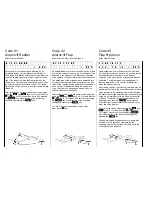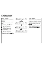
Code 72 ALARM TIMER and Code 97
MIX-only Channel Stopwatch Stopwatch
Mix-only Channel Set-up Stopwatch
32
M I X O N L Y C H
n o
Code 72 permits interrupting the normal direct signal
flow between the control function inlets and the
associated control channels at the outlet side. The
signal generators connected to the control function
inlets concerned will then affect the mixer inputs of
the channel in question, but not the allocated servo.
The latter can then be reached by mixers
programmed for their specific control channels. Using
this arrangement, it is possible to utilise the signal
generator and servo of one or more channels
independently of each other for optional special
functions.
It permits, for example in F3B model types to use
channel 1 via the dummy function of a special
functions mixer to operate “butterfly mode”, controlled
by the throttle/spoiler stick, provided spoilers have not
been installed.
In the case where spoilers have been installed and
“butterfly mode” with or without spoilers is to be
provided for experimentation purposes, a mixer can
be operated in normal mode. With the aid of code 33,
this connection can be turned on and off. The same
applies to other applications.
Any channel can be switched between normal and
mix-only mode by keys
1
…
9
. All channels can be
switch back to normal by pressing the
CLEAR
key.
The PROFI-ULTRASOFT-Module offers two
stopwatch functions.
1. Stopwatch with normal display (hours,
minutes and seconds).
2. Timer alert, with seconds display.
One of these options can be selected for each model
program.
A stopwatch, once programmed, will appear on the
lower line of the display each time the transmitter is
turned on, it does not need to be called over and over
again. Once triggered the stopwatch will continue to
run even when inputs are made during its operation
via the keyboard.
Stopwatch with normal display.
The stopwatch with normal display may be
programmed by allocating a switch to function “CLK”
using code 23. A prerequisite is that the alarm timer
(code 97) is not activated. The clock will then run as
long as the allocated switch is closed. Using the
CLEAR
key it can be reset to 0.00.00 when not
running (if running the transmitter switches to list of
codes mode of operation). By this programmable
switch allocation, the stopwatch function may be
coupled with the tow hook, permitting the exact
duration of flight (starting from release of the tow-line)
to be recorded.
T I M E R 6 0 0 s e c
A L A R M 3 0 s e c
After calling code 97, the message “TIMER OFF” will
appear on the display. The timer is activated by the
INC
or
DEC
key, whereby the stopwatch, possibly
programmed by code 23, will be turned off. The alarm
timer can be deactivated by the
CLEAR
key. Timer
run can be adjusted on the upper line of the display in
10 second increments using the
INC
and
DEC
keys. In the lower line a point of time can be set
when, prior to the expiration of the return time, an
acoustic signal alerts the flyer. The arrow at the right
hand end of the display indicates which time can
currently be adjusted, and is moved by pressing the
TURN
key.
After the set time has run down to 0, it is indicated by
a longer acoustic signal. The timer continues to run,
so that the time beyond 0 can be read.
Start/Stop instructions can be given by keys
2
and
3
respectively, or via an intermediate switch (order
No. 4160/11) connected to plug station CLK, or a kick
button (order No. 4144).
If a switch for the timer has been allocated by code
23, operation of the alarm timer will be performed
exclusively by that switch.
Acoustic Signal Sequence:
100s before zero: every 5 seconds
20s before zero: every 2 seconds
10s before zero: every second
0s Extended Signal
A + symbol on the display indicates that the time
shown is that beyond zero. The maximum timer
capacity is 900 seconds beyond zero.
Summary of Contents for mc-18
Page 1: ...1...
Page 10: ...Block Diagram NORMAL 10...
Page 11: ...Block Diagram NORMAL DIFF 11...
Page 12: ...Block Diagram DELTA DIFF 12...
Page 13: ...Block Diagram UNIFLY DIFF 13...
Page 14: ...Block Diagram Quadro Flap 14...
Page 15: ...Block Diagram F3B 3 wing servos 15...


