Codes of the PROFI-ULTRASOFT-MODULE
4
Model Type Display Reads
Meaning
Described on
Code
Fixed-Wing Helicopter
1-5 6,7 8 9
Page
Page
11 11 11 11
REVERSE SW
Direction of Rotation of Servos
21
65
12 12 12 12
THROW ADJUST
Servo Throw Adjustments
22
75
13 13 13 13
DUAL RATE
Switchable Servo Throw Reduction
24
77
14 14 14 14
EXPONENTIAL
Exponential Servo Movement
24
77
15 15 15 15
SUB TRIM
Servo Neutral Po int Adjust
22
76
16 16 16 16
TRACE RATE
Adjust Effect of Operating Stick
23
76
17
RED. THROTTLE
Switchable Throttle Reduction
28
18 18
IDLE R. TRIM
Idle Trim Adjustment
19
19 19 19 19
THROW LIMIT
Servo Throw Reduction
22
76
21 21
GAS STICK DR
Direction of Pitch Control
61
22 22
DIFF. RATE
Aileron Differential
27
23 23 23 23
SWITCH FUNCT.
External Switch Allocation
20, 38
62
24 24
AUTO ROTATION
Autorotation Changeover Set -up
66
25 25
INV. FLIGHT
Set-up for Inverted Flight
66
26 26
HIGH PITCH
Maximum Pitch Set -up
67
27 27
LOW PITCH
Minimum Pitch Set
67
28 28
HOV. PITCH
Hover. Pitch Set
67
29 29
THROTTLE TRIM
Allocation of Idle Trim
62
31 31
THR/BRK MIDP
Set Channel 1 Mid -Point
23
32 32 32 32
MODEL NAME
Input Mod el Name
19
61
33 33 33 33
SWITCH MIX
Allocation of Mix Switches
30
80
34 34 34 34
SWITCH DR/EXP
Dual Rate/Exponential Switch Set -up
24
63
35 35 35 35
RED. TRIM
Allows Reduction of Trim Range
25
78
37 37 37 37
INP-PORT ASS
Allocation of External Contr ols
21
65
41
AILE RUDD
Aileron to Rudder Mix
40
42
AILE FLAP
Aileron to Flap Mix
40
43 43
V-TAIL SW
V-Tail Mixer
21
44
BRK ELEV
Spoiler to Elevator Mix
43
45
BRK FLAP
Spoiler to Flap Mix
43
46
BRK AILERON
Spoiler to Aileron Mix
43
47
ELEV FLAP
Elevator to Flap Mix
42
48
FLAP ELEV
Flap to Elevator Mix
42
49
FLAP AILERON
Flap to Aileron Mix
40
51 51 51 51
MIXx CHANNEL
Channel Allocation for Mixers
30
80
52
STRT-SPD-DIST
Flight Trim: Start, Speed, Distance
39
53
FLAP TRIM ASS
Flap Trim Assignment
39
54
DIFF REDUCT
Reduction of Aileron Differential
43
56 56 56 56
MODEL SELECT
Select Model
18
60
Model Type Display Reads
Meaning
Described on
Code
Fixed-Wing Helicopter
1-5 6,7 8 9
Page
Page
57 57 57 57
MODE SELECT
Stick Mode Selection
18
60
58 58 58 58
MODEL TYPE
Model Type Selection
19
61
59 59 59 59
TRIM OFFSET
Storage of Trim Offset Values
25
82
61 61 61 61
MIXx COM GAIN
Mixer No x Common Gain Adjust
30
80
63 63 63 63
CH1-SWITCH
Channel 1 Dependant Auto Switch
29
79
66
PROGRAM-AUTOM
Automatic Manoeuvre Set -up
28
67 67
ATS SELECT
Automatic Torque System S elect
66
68 68
SWASH TYPE
Swashplate Type Selection
64
69 69
SWASH ADJUST
Swashplate Mixer Adjustment
65
71 71 71 71
MIXx SEP GAIN
Mixer No x Separate Gain Adjust
30
80
72 72
MIX ONLY CH
Allows Isolation of Control from O/P
32
73 73 73 73
SWITCH POSIT.
Display of Switch Positions
36
84
74 74 74 74
SERVO POSIT.
Display of a Servo Position
35
83
75 75
SWSH RUDD MIX
Swashplate to Tail Rotor Mix
75
76 76 76 76
SERVO TEST
Allows Testing of Servos
35
83
77 77 77 77
FAIL SAFE MEM
Set-up of Failsafe Mode
33
84
78 78 78 78
FAIL SAFE BAT
Failsafe on Low RX Battery
34
85
79 79 79 79
SERVO SLOW-D
Servo Slow Set -up
23
78
81 81
STATIC ATS
Static Torque Compensation
68
82
DYNAMIC ATS
Dynamic Torque Compensation
68
83 83
AUTOR. Rud-of
Positions Tail Rotor in Auto -Rot’n
69
84
HOV. THROTTLE
Set-up Throttle for Hover
69
85
IDLE UP
Set-up Throttle P resets
70
86
SWSH THRO MIX
Swashplate to Throttle Mix
72
87
RUDD THRO MIX
Tail Rotor to Throttle Mix
72
88 88 88 88
KEYBOARD LOCK
Lock the Keyboard
34
86
89 89
GYRO CONTROL
Set-up Gyro
72
91 91 91
AN. TRIM SW
Set-up for PROFITRIM
42
75
92 92 92
SMOOTH SWITCH
Servo Transit Time Set -up
39
78
93 93
SWASH ROTATE
Enter Swashplate Rotation
68
94 94 94 94
COPY MODEL
Model Copy Facility
26
82
95 95 95 95
MODULATION
PPM/PCM Select
18
60
97 97 97 97
ALARM TIMER
Stop Watch Timer
32
85
98 98 98 98
INTEG. TIME
TX operating Timer
33
86
99 99 99 99
ALL CLOSE
Lock the Transmitter
34
86
Summary of Contents for mc-18
Page 1: ...1...
Page 10: ...Block Diagram NORMAL 10...
Page 11: ...Block Diagram NORMAL DIFF 11...
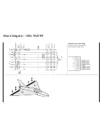
Page 12: ...Block Diagram DELTA DIFF 12...
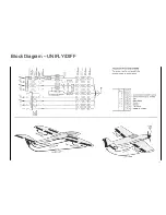
Page 13: ...Block Diagram UNIFLY DIFF 13...
Page 14: ...Block Diagram Quadro Flap 14...
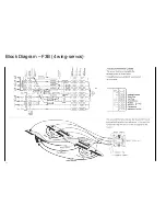
Page 15: ...Block Diagram F3B 3 wing servos 15...


