Code 22
Differential
Aileron Differential in Type 2 – 7 Models
27
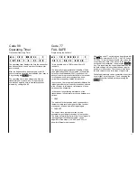
m c - 1 8 E M O D E L 1
A I L E D I F 0 N O R M
Differentiation of ailerons serves to correct an
undesirable effect called “adverse yaw”. With equal
throws on ailerons the drag of the lowered aileron is
higher than the drag created by the raised one. The
resulting moment about the vertical axis acts in
opposite direction to the planned direction of flight. If
a model tries to turn to starboard (right) under the
action of the ailerons, higher drag is generated on the
port (left) side, causing the model to bank to
starboard, yet yawing left about the vertical axis at the
same time. This effect which us much more apparent
with sailplanes, with their high aspect ratio wings and
resulting longer lever arms as compare to power
models, normally has to be compensated for by
simultaneous deflection of rudder, which increases
drag still more and impairs flight performance.
In the case of differential ailerons the downward
movement of an aileron is less than the upward
movement of the opposing aileron. This results in the
drag being equal on both sides and in the
cancellation of the negative jawing moment.
Mechanical solutions usually require permanent
adjustments to be made during the assembly of the
model, and in the case of high differential ratios may
well introduce slop into the control system.. Electronic
differential offers great advantages; each of the
ailerons is operated by a separate servo, permitting
the ailerons servo to be installed in the wing, ensuring
slop free and reproducible adjustments even with 2
piece wings.
The ratio of differential can be adjusted as required
via the downward deflection without affecting upward
deflection permitting complete suppression of
downward motion (Split) in extreme cases. In this
manner, one can not only cancel the negative yawing
motion moment, but even generate a positive one. In
this latter case, operation of the ailerons will make the
model yaw towards the direction of turn, permitting
even large sailplanes to perform smooth turns on
ailerons alone, which would not be possible
otherwise.
The PROFI-ULTRASOFT-Module permits storing
three different differential ratios which can be called
up via allocated switches via code 23. Use of a
external differential switch, order N° 4160/22, with
three positions is recommended. This permits
switching between the three differential values, e.g.
switch position 0 = 20% differential used for
aerobatics to allow precision rolls, switch position 1 =
50% for assisting the model during thermalling, and
finally switch position 2 = 100% (split) for performing
turns on ailerons alone at the slope.
After input of code 22, the number of the differential
memory (0 – 2) and the stored value in % will appear
in the lower line of the display, with 0% representing
the standard installation (no differential) and 100%
the split function. After changing the switch position
into the required position, the desired value can be
set via the
INC
and
DEC
keys. Resetting to the
normal setting (0%) is performed by pressing the
CLEAR
key.
Summary of Contents for mc-18
Page 1: ...1...
Page 10: ...Block Diagram NORMAL 10...
Page 11: ...Block Diagram NORMAL DIFF 11...
Page 12: ...Block Diagram DELTA DIFF 12...
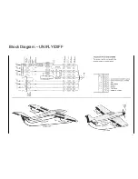
Page 13: ...Block Diagram UNIFLY DIFF 13...
Page 14: ...Block Diagram Quadro Flap 14...
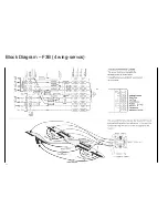
Page 15: ...Block Diagram F3B 3 wing servos 15...

